
User manual


Table Of Contents
- 1 Table of contents1 T
- 2 Package Contents
- 3 Introduction
- 4 System overview
- 5 Control Surfaces
- 6 AXUM Engine
- 6.1 Console 1-4 configuration
- 6.1.1 IP/Clock configuration
- 6.1.2 Global configuration
- 6.1.3 Mix buss configuration
- 6.1.4 Monitor buss configuration
- 6.1.5 Source configuration
- 6.1.6 Extern source configuration
- 6.1.7 Destination configuration
- 6.1.8 Talkback configuration
- 6.1.9 Processing presets
- 6.1.10 Module assignment
- 6.1.11 Module configuration
- 6.1.11.1 Module configuration page
- 6.1.11.2 Module preset 1A/1B, 2A/2B, 3A/3B, 4A/4B
- 6.1.11.3 Processing
- These are the programmed processing defaults for the modules. Depending on the startup settings these processing defaults will be used at startup (programmed defaults in global configuration).The field ‘Use at source select’ determines if the default module processing in the source configuration is used when a source is assigned via the module source select functionality and no processing preset is assigned in the ‘source configuration’.
- The following state/value processing sections are available:
- 6.1.11.4 Routing
- 6.1.11.5 Set module 1 to programmed startup state
- 6.1.12 Mix/monitor buss presets
- 6.1.13 Console presets
- 6.1.14 Surface configuration
- 6.1.15 Rack configuration
- 6.1.16 Source pools
- 6.1.17 Preset pools
- 6.1.18 Users
- 6.2 System configuration
- 6.1 Console 1-4 configuration
- 7 Surface(s) website
- 8 Block diagrams – Must be created
- 9 I/O Rack description
- 10 Available I/O rack cards
- 11 Patch panels
- 12 Specifications AXUM digital audio system
- 13 List Of Figures
- 14 List Of Tables
- 15 Declaration Of Conformity
- 16 Product Safety
- 17 Disclaimer
- 18 Appendix A - Network design for AXUM
- 19 Appendix B – Surface service
- 20 Appendix C – Engine functions
A·X·U·M User Manual Version 2.5 - 2011-01-28
AXUM from D&R - Phone: +31 294 418014 - E-Mail: info@d-r.nl - 38 -
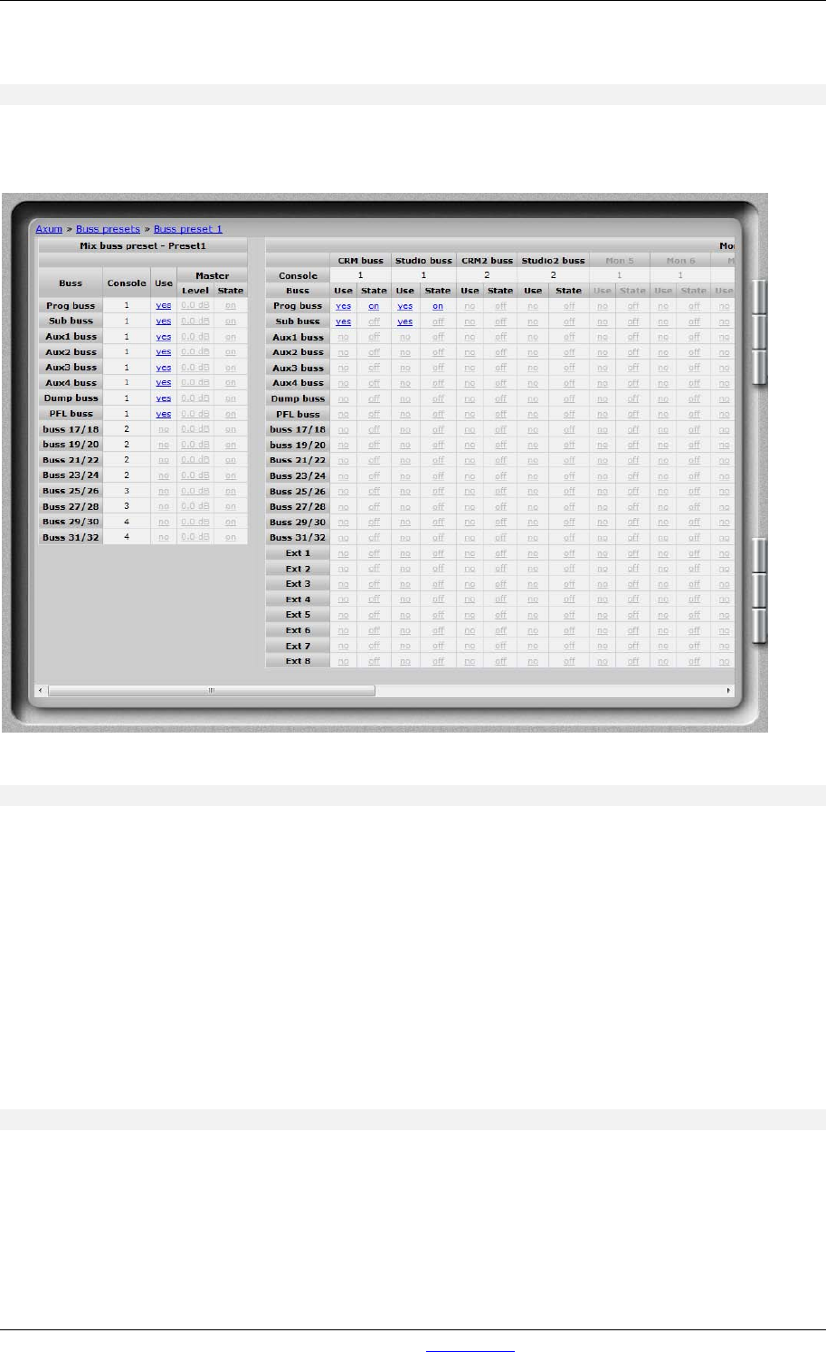
6.1.12.1 Settings
On this page you can set the required levels and state for all busses and monitor busses which are
used in the mix/monitor buss preset.
Figure 22: Mix/monitor buss preset settings
6.1.12.2 Mix buss settings
• Console
Displays the console where this mix buss is assigned to.
• Use
When set to ‘yes’ the settings for this mix buss overrides the current mix settings if the preset
is loaded.
• Master level
Here you can give the preset master level of the corresponding mix buss.
• Master state
Here you can give the preset master state of the corresponding mix buss.
6.1.12.3 Monitor buss settings
• Console
Displays the console where this monitor buss is assigned to.
• Use
When set to ‘yes’ the settings for this monitor buss overrides the current monitor settings if the
preset is loaded.