
User manual


Table Of Contents
- 1 Table of contents1 T
- 2 Package Contents
- 3 Introduction
- 4 System overview
- 5 Control Surfaces
- 6 AXUM Engine
- 6.1 Console 1-4 configuration
- 6.1.1 IP/Clock configuration
- 6.1.2 Global configuration
- 6.1.3 Mix buss configuration
- 6.1.4 Monitor buss configuration
- 6.1.5 Source configuration
- 6.1.6 Extern source configuration
- 6.1.7 Destination configuration
- 6.1.8 Talkback configuration
- 6.1.9 Processing presets
- 6.1.10 Module assignment
- 6.1.11 Module configuration
- 6.1.11.1 Module configuration page
- 6.1.11.2 Module preset 1A/1B, 2A/2B, 3A/3B, 4A/4B
- 6.1.11.3 Processing
- These are the programmed processing defaults for the modules. Depending on the startup settings these processing defaults will be used at startup (programmed defaults in global configuration).The field ‘Use at source select’ determines if the default module processing in the source configuration is used when a source is assigned via the module source select functionality and no processing preset is assigned in the ‘source configuration’.
- The following state/value processing sections are available:
- 6.1.11.4 Routing
- 6.1.11.5 Set module 1 to programmed startup state
- 6.1.12 Mix/monitor buss presets
- 6.1.13 Console presets
- 6.1.14 Surface configuration
- 6.1.15 Rack configuration
- 6.1.16 Source pools
- 6.1.17 Preset pools
- 6.1.18 Users
- 6.2 System configuration
- 6.1 Console 1-4 configuration
- 7 Surface(s) website
- 8 Block diagrams – Must be created
- 9 I/O Rack description
- 10 Available I/O rack cards
- 11 Patch panels
- 12 Specifications AXUM digital audio system
- 13 List Of Figures
- 14 List Of Tables
- 15 Declaration Of Conformity
- 16 Product Safety
- 17 Disclaimer
- 18 Appendix A - Network design for AXUM
- 19 Appendix B – Surface service
- 20 Appendix C – Engine functions
A·X·U·M User Manual Version 2.5 - 2011-01-28
AXUM from D&R - Phone: +31 294 418014 - E-Mail: info@d-r.nl - 21 -
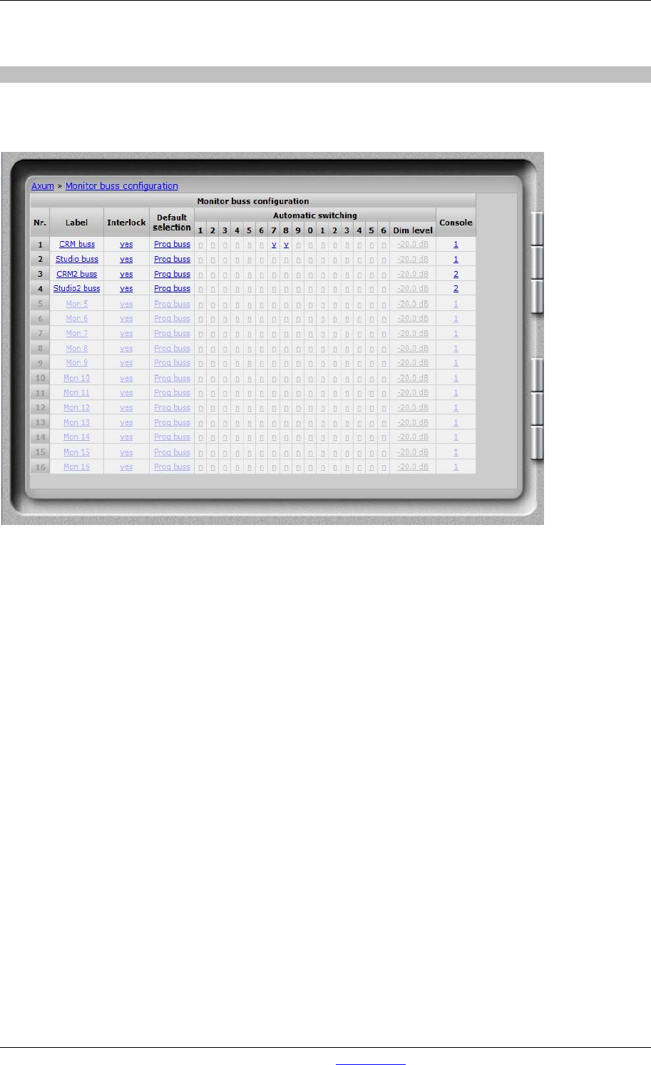
6.1.4 Monitor buss configuration
Per DSP card, you have 4 stereo monitor busses that can be used. They need a name, console
assignment and configuration so they can work properly:
Figure 9: Monitor buss configuration
• Label
Here you give a name to this monitor buss
• Interlock
Yes means only one source is active at the same time, on this monitor buss.
• Default selection
If the last selected source is turned off it will always go to the default selection.
This selection is also your startup default.
• Automatic switching.
You can tell the Engine that a monitor buss switches automatically when the ‘source buss’ is
activated. Also known as ‘PFL to CRM’. If you have two separate studios’ you can have
multiple automatically switched busses (e.g. PFL 1 and PFL 2).
When to mix buss is an exclusive buss, the monitor buss will also switch ‘exclusive’; normally
automatic switching will be summing with the set up ‘Dim level’.
• Dim level
When you have set the monitor buss to switch automatically, the source signal is dimmed by
the filled in level and the buss that is switched on to the Monitor buss is at unity gain (0 dB).
• Console
You can select to which console a monitor buss belongs.