
User manual


Table Of Contents
- 1 Table of contents1 T
- 2 Package Contents
- 3 Introduction
- 4 System overview
- 5 Control Surfaces
- 6 AXUM Engine
- 6.1 Console 1-4 configuration
- 6.1.1 IP/Clock configuration
- 6.1.2 Global configuration
- 6.1.3 Mix buss configuration
- 6.1.4 Monitor buss configuration
- 6.1.5 Source configuration
- 6.1.6 Extern source configuration
- 6.1.7 Destination configuration
- 6.1.8 Talkback configuration
- 6.1.9 Processing presets
- 6.1.10 Module assignment
- 6.1.11 Module configuration
- 6.1.11.1 Module configuration page
- 6.1.11.2 Module preset 1A/1B, 2A/2B, 3A/3B, 4A/4B
- 6.1.11.3 Processing
- These are the programmed processing defaults for the modules. Depending on the startup settings these processing defaults will be used at startup (programmed defaults in global configuration).The field ‘Use at source select’ determines if the default module processing in the source configuration is used when a source is assigned via the module source select functionality and no processing preset is assigned in the ‘source configuration’.
- The following state/value processing sections are available:
- 6.1.11.4 Routing
- 6.1.11.5 Set module 1 to programmed startup state
- 6.1.12 Mix/monitor buss presets
- 6.1.13 Console presets
- 6.1.14 Surface configuration
- 6.1.15 Rack configuration
- 6.1.16 Source pools
- 6.1.17 Preset pools
- 6.1.18 Users
- 6.2 System configuration
- 6.1 Console 1-4 configuration
- 7 Surface(s) website
- 8 Block diagrams – Must be created
- 9 I/O Rack description
- 10 Available I/O rack cards
- 11 Patch panels
- 12 Specifications AXUM digital audio system
- 13 List Of Figures
- 14 List Of Tables
- 15 Declaration Of Conformity
- 16 Product Safety
- 17 Disclaimer
- 18 Appendix A - Network design for AXUM
- 19 Appendix B – Surface service
- 20 Appendix C – Engine functions
A·X·U·M User Manual Version 2.5 - 2011-01-28
AXUM from D&R - Phone: +31 294 418014 - E-Mail: info@d-r.nl - 20 -
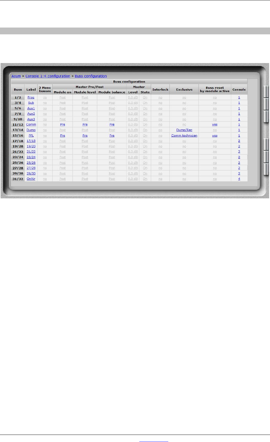
6.1.3 Mix buss configuration
You have to setup the busses to create the names, console assignment and functionality of the
Busses. Here we see the setup for a single console buss setup:
Figure 8: Buss configuration
• Label
The name given to this buss.
• 2 Mono busses
It is possible to make 2 mono busses from one stereo buss. All buss-sends, to this buss, on
the module’s will now include stereo to mono summing.
• Master pre/post
You can choose the buss to be pre or post ON, level (comparable with pre/post fader) and
balance (could be your pan-pot).
• Master level/state
This setting is used as programmed startup level, so the buss masters are in a known state.
• Interlock
If you make a buss interlock, only 1 module can be assigned at the same time.
• Exclusive
When routing to an Dump/Rec exclusive buss is made, the routing to all other busses on that
module will be disabled. This is useful for a so called ‘dump buss’.
The selections Comm technician and Comm producer are used if you want to make a
communication buss. Such buss makes it possible to let presenters talk with hybrid or to talk
with an technician/producer.
• Buss reset
This setting can be used to create a CUE/PFL buss with auto-reset (CUE Reset).
If you have multiple studios and CUE/PFL busses you may assign reset to multiple busses.
• Console
You can select to which console a buss belongs.