
User manual


Table Of Contents
- 1 Table of contents1 T
- 2 Package Contents
- 3 Introduction
- 4 System overview
- 5 Control Surfaces
- 6 AXUM Engine
- 6.1 Console 1-4 configuration
- 6.1.1 IP/Clock configuration
- 6.1.2 Global configuration
- 6.1.3 Mix buss configuration
- 6.1.4 Monitor buss configuration
- 6.1.5 Source configuration
- 6.1.6 Extern source configuration
- 6.1.7 Destination configuration
- 6.1.8 Talkback configuration
- 6.1.9 Processing presets
- 6.1.10 Module assignment
- 6.1.11 Module configuration
- 6.1.11.1 Module configuration page
- 6.1.11.2 Module preset 1A/1B, 2A/2B, 3A/3B, 4A/4B
- 6.1.11.3 Processing
- These are the programmed processing defaults for the modules. Depending on the startup settings these processing defaults will be used at startup (programmed defaults in global configuration).The field ‘Use at source select’ determines if the default module processing in the source configuration is used when a source is assigned via the module source select functionality and no processing preset is assigned in the ‘source configuration’.
- The following state/value processing sections are available:
- 6.1.11.4 Routing
- 6.1.11.5 Set module 1 to programmed startup state
- 6.1.12 Mix/monitor buss presets
- 6.1.13 Console presets
- 6.1.14 Surface configuration
- 6.1.15 Rack configuration
- 6.1.16 Source pools
- 6.1.17 Preset pools
- 6.1.18 Users
- 6.2 System configuration
- 6.1 Console 1-4 configuration
- 7 Surface(s) website
- 8 Block diagrams – Must be created
- 9 I/O Rack description
- 10 Available I/O rack cards
- 11 Patch panels
- 12 Specifications AXUM digital audio system
- 13 List Of Figures
- 14 List Of Tables
- 15 Declaration Of Conformity
- 16 Product Safety
- 17 Disclaimer
- 18 Appendix A - Network design for AXUM
- 19 Appendix B – Surface service
- 20 Appendix C – Engine functions
A·X·U·M User Manual Version 2.5 - 2011-01-28
AXUM from D&R - Phone: +31 294 418014 - E-Mail: info@d-r.nl - 11 -
4.4 Principle of operation
4.4.1 AXUM system
The AXUM system will be build up around the matrix/router that gives a lot of routing flexibility. Up to 4
DSP cards can be inserted to create mixing power as requested. For example, you can create with
one AXUM system (equipped with one DSP card):
- A single mixing console with 32 stereo modules and 16 stereo busses
- Multiple mixing consoles (maximal 4), 3 consoles are used in our example:
1 consoles with 16 stereo modules and 6 stereo busses
1 consoles with 12 stereo modules and 6 stereo busses
1 console 4 stereo modules and 4 stereo busses
This makes clear we do not talk over a ‘mixing console’, the AXUM is an audio-platform!
Depending on the configuration, you can make your own studio console(s)/surface functionality. Al this
power is controlled and configured by the AXUM engine. This engine configuration is described in
detail later on.
4.4.2 Mixing console
As mentioned before the configuration is done within the Axum engine, now we will give a short
overview/introduction on the structure of the mixing console(s) platform solution of the engine.
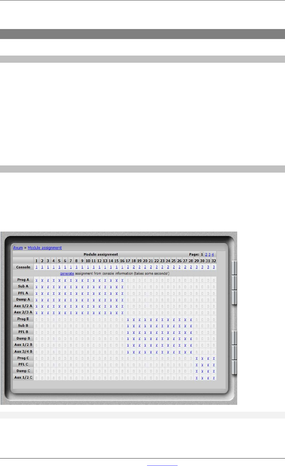
For the configuration of the busses, monitor busses and modules you can setup to which console it
should belong (1-4). Finally the engine will extract a ‘assignment’ picture from this information which
shows clearly the console blocks.