
User manual


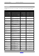
Table Of Contents
- 1 Table of contents1 T
- 2 Package Contents
- 3 Introduction
- 4 System overview
- 5 Control Surfaces
- 6 AXUM Engine
- 6.1 Console 1-4 configuration
- 6.1.1 IP/Clock configuration
- 6.1.2 Global configuration
- 6.1.3 Mix buss configuration
- 6.1.4 Monitor buss configuration
- 6.1.5 Source configuration
- 6.1.6 Extern source configuration
- 6.1.7 Destination configuration
- 6.1.8 Talkback configuration
- 6.1.9 Processing presets
- 6.1.10 Module assignment
- 6.1.11 Module configuration
- 6.1.11.1 Module configuration page
- 6.1.11.2 Module preset 1A/1B, 2A/2B, 3A/3B, 4A/4B
- 6.1.11.3 Processing
- These are the programmed processing defaults for the modules. Depending on the startup settings these processing defaults will be used at startup (programmed defaults in global configuration).The field ‘Use at source select’ determines if the default module processing in the source configuration is used when a source is assigned via the module source select functionality and no processing preset is assigned in the ‘source configuration’.
- The following state/value processing sections are available:
- 6.1.11.4 Routing
- 6.1.11.5 Set module 1 to programmed startup state
- 6.1.12 Mix/monitor buss presets
- 6.1.13 Console presets
- 6.1.14 Surface configuration
- 6.1.15 Rack configuration
- 6.1.16 Source pools
- 6.1.17 Preset pools
- 6.1.18 Users
- 6.2 System configuration
- 6.1 Console 1-4 configuration
- 7 Surface(s) website
- 8 Block diagrams – Must be created
- 9 I/O Rack description
- 10 Available I/O rack cards
- 11 Patch panels
- 12 Specifications AXUM digital audio system
- 13 List Of Figures
- 14 List Of Tables
- 15 Declaration Of Conformity
- 16 Product Safety
- 17 Disclaimer
- 18 Appendix A - Network design for AXUM
- 19 Appendix B – Surface service
- 20 Appendix C – Engine functions

A·X·U·M User Manual Version 2.5 - 2011-01-28
AXUM from D&R - Phone: +31 294 418014 - E-Mail: info@d-r.nl - 107 -
Function name
comments
Example object to connect to
Version
Buss 25/26 on
Select the buss on
Switch
2.2
Buss 25/26 off Select the buss off Switch 2.2
Buss 25/26 on/off
Select the buss on/off
Switch
2.0
Buss 25/26 pre
Select if this module sent pre or post fader signal to
the buss
Switch
2.0
Buss 25/26 balance
The balance of the module signal sent to the buss
Encoder
2.0
Buss 25/26 balance
reset
This resets the balance to the center position Switch 2.0
Buss 27/28 level
Controls the sent level to the buss for this module
Encoder, Fader
2.0
Buss 27/28 level
reset
Select ‘Off ‘or ‘On = 0 dB’ depending on current state
Encoder Switch
2.0
Buss 27/28 on
Select the buss on
Switch
2.2
Buss 27/28 off
Select the buss off
Switch
2.2
Buss 27/28 on/off
Select the buss on/off
Switch
2.0
Buss 27/28 pre
Select if this module sent pre or post fader signal to
the buss
Switch
2.0
Buss 27/28 balance
The balance of the module signal sent to the buss
Encoder
2.0
Buss 27/28 balance
reset
This resets the balance to the center position
Switch
2.0
Buss 29/30 level
Controls the sent level to the buss for this module
Encoder, Fader
2.0
Buss 29/30 level
reset
Select ‘Off ‘or ‘On = 0 dB’ depending on current state
Encoder Switch
2.0
Buss 29/30 on
Select the buss on
Switch
2.2
Buss 29/30 off
Select the buss off
Switch
2.2
Buss 29/30 on/off
Select the buss on/off
Switch
2.0
Buss 29/30 pre
Select if this module sent pre or post fader signal to
the buss
Switch
2.0
Buss 29/30 balance
The balance of the module signal sent to the buss
Encoder
2.0
Buss 29/30 balance
reset
This resets the balance to the center position
Switch
2.0
Buss 31/32 level
Controls the sent level to the buss for this module
Encoder, Fader
2.0
Buss 31/32 level
reset
Select ‘Off ‘or ‘On = 0 dB’ depending on current state Encoder Switch 2.0
Buss 31/32 on
Select the buss on
Switch
2.2
Buss 31/32 off
Select the buss off
Switch
2.2
Buss 31/32 on/off
Select the buss on/off
Switch
2.0
Buss 31/32 pre Select if this module sent pre or post fader signal to
the buss
Switch 2.0
Buss 31/32 balance
The balance of the module signal sent to the buss
Encoder
2.0
Buss 31/32 balance
reset
This resets the balance to the center position
Switch
2.0
Source start
Start (GPO) for current source
Switch
2.0
Source stop
Stop (GPO) for current source
Switch
2.0
Source start/stop
Toggle between start/stop for current source
Switch
2.0
Cough on/off
Toggle between Cough On and Cough off.
GPI, Switch
2.0
Source alert
Do/signal a alert from the selected source
GPI, Switch
2.0
Control Control 1-4 data value (1-4 depends on console
number for this module)
The data interpretation depends on the mode of this
control (source, gain, aux level etc. etc)
Encoder 2.1
Control label
Set label of the current selected control 1-4 mode (1-
4 depends on console number for this module)
(Source, gain, aux level etc. etc)
Display
2.1
Control reset
Sets the data to the control 1-4 default value or toggle
functions (1-4 depends on console number for this
module).
The data interpretation depends on the mode of this
control (source, gain, aux level etc. etc)
Encoder switch
2.1
Control 1
Control 1 data value
The data interpretation depends on the mode of this
control 1 (source, gain, aux level etc. etc)
Encoder
2.0
Control 1 label Set label of the current selected control 1 mode
(Source, gain, aux level etc. etc)
Display 2.0
Control 1 reset
Sets the data to the control 1 default value
The data interpretation depends on the mode of this
control 1 (source, gain, aux level etc. etc)
Encoder switch
2.0
Control 2 Control 2 data value
The data interpretation depends on the mode of this
control 2 (source, gain, aux level etc. etc)
Encoder 2.0
Control 2 label Set label of the current selected control 2 mode
(Source, gain, aux level etc. etc)
Display 2.0