
User manual


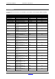
Table Of Contents
- 1 Table of contents1 T
- 2 Package Contents
- 3 Introduction
- 4 System overview
- 5 Control Surfaces
- 6 AXUM Engine
- 6.1 Console 1-4 configuration
- 6.1.1 IP/Clock configuration
- 6.1.2 Global configuration
- 6.1.3 Mix buss configuration
- 6.1.4 Monitor buss configuration
- 6.1.5 Source configuration
- 6.1.6 Extern source configuration
- 6.1.7 Destination configuration
- 6.1.8 Talkback configuration
- 6.1.9 Processing presets
- 6.1.10 Module assignment
- 6.1.11 Module configuration
- 6.1.11.1 Module configuration page
- 6.1.11.2 Module preset 1A/1B, 2A/2B, 3A/3B, 4A/4B
- 6.1.11.3 Processing
- These are the programmed processing defaults for the modules. Depending on the startup settings these processing defaults will be used at startup (programmed defaults in global configuration).The field ‘Use at source select’ determines if the default module processing in the source configuration is used when a source is assigned via the module source select functionality and no processing preset is assigned in the ‘source configuration’.
- The following state/value processing sections are available:
- 6.1.11.4 Routing
- 6.1.11.5 Set module 1 to programmed startup state
- 6.1.12 Mix/monitor buss presets
- 6.1.13 Console presets
- 6.1.14 Surface configuration
- 6.1.15 Rack configuration
- 6.1.16 Source pools
- 6.1.17 Preset pools
- 6.1.18 Users
- 6.2 System configuration
- 6.1 Console 1-4 configuration
- 7 Surface(s) website
- 8 Block diagrams – Must be created
- 9 I/O Rack description
- 10 Available I/O rack cards
- 11 Patch panels
- 12 Specifications AXUM digital audio system
- 13 List Of Figures
- 14 List Of Tables
- 15 Declaration Of Conformity
- 16 Product Safety
- 17 Disclaimer
- 18 Appendix A - Network design for AXUM
- 19 Appendix B – Surface service
- 20 Appendix C – Engine functions

A·X·U·M User Manual Version 2.5 - 2011-01-28
AXUM from D&R - Phone: +31 294 418014 - E-Mail: info@d-r.nl - 103 -
20 Appendix C – Engine functions
The engine houses all mixing console functions and is able to connect various objects to its function
as has been described in the previous chapters. Below we give a list of all available functions within
the engine.
20.1 Modules
If four DSP cards are inserted, it is possible to have 128 modules (32 stereo modules per DSP card).
For each module, you are able to connect objects to the following functions:
Function name
comments
Example object to connect to
Version
Label
Label of the module
Display
2.0
Source
Steps through the source list at the current module
Encoder, Display
2.0
Module preset A
Select the pre configured module preset 1A, 2A, 3A
or 4A. (Which of the 4 depends on the last console
preset used).
Switch
2.2
Module preset B
Select the pre configured module preset 1B, 2B, 3B
or 4B. (Which of the 4 depends on the last console
preset used).
Switch
2.2
Module preset A/B
Toggle the pre configured module preset 1A/1B,
2A/2B, 3A/3B or 4A/4B. (Which of the 4 depends on
the last console preset used).
Switch
2.2
Module preset 1A
Select the pre configured Module preset 1A
Switch
2.1
Module preset 1B
Select the pre configured Module preset 1B
Switch
2.1
Module preset 2A
Select the pre configured Module preset 2A
Switch
2.1
Module preset 2B
Select the pre configured Module preset 2B
Switch
2.1
Module preset 3A
Select the pre configured Module preset 3A
Switch
2.1
Module preset 3B Select the pre configured Module preset 3B Switch 2.1
Module preset 4A
Select the pre configured Module preset 4A
Switch
2.1
Module preset 4B
Select the pre configured Module preset 4B
Switch
2.1
Source phantom
Toggles phantom power on the source routed to this
module
Switch
2.0
Source pad Toggles PAD on the source routed to this module Switch 2.0
Source gain level
changes (analog) gain on the source routed to this
module
Encoder
2.0
Source gain level
reset
changes (analog) gain on the source routed to this
module
Switch
2.0
Insert on/off
Switches the insert return on/off
Switch
2.0
Phase
Change phase of all channels in the module
Switch
2.0
Phase on/off
Switches the phase on/off
Switch
2.1
Gain level
Controls the gain in steps of 0.1 dB
Encoder, Display
2.0
Gain level reset
Sets the gain to 0 dB
Encoder switch
2.0
Low cut frequency Low cut frequency control. Encoder, Display 2.0
Low cut on/off
Select the low cut on/off
Switch
2.0
EQ Band 1 Level
Controls the EQ level in steps of 0.1 dB
Encoder
2.0
EQ Band 1
Frequency
Controls the EQ frequency
Encoder
2.0
EQ Band 1
Bandwidth
Controls the EQ bandwidth Encoder 2.0
EQ Band 1 Level
reset
Sets the EQ level to the band default
Encoder Switch
2.0
EQ Band 1
Frequency reset
Sets the EQ frequency to the band default
Encoder Switch
2.0
EQ Band 1
Bandwidth reset
Sets the EQ bandwidth to the band default
Encoder Switch
2.0
EQ Band 1 Type
Steps through the EQ band types available
Encoder
2.0
EQ Band 2 Level
Controls the EQ level in steps of 0.1 dB
Encoder
2.0
EQ Band 2
Frequency
Controls the EQ frequency Encoder 2.0
EQ Band 2
Bandwidth
Controls the EQ bandwidth
Encoder
2.0
EQ Band 2 Level
reset
Sets the EQ level to the band default
Encoder Switch
2.0
EQ Band 2
Frequency reset
Sets the EQ frequency to the band default
Encoder Switch
2.0