
Hardware reference guide


DSN-1100 Hardware Reference Guide 33
Table A-1. xStack Storage Array DIMM Specifications
Requirement Description
PC2700/DDR333 speed SDRAMs must be JEDEC compliant and DDR333 capable, with a CAS latency of 2.5.
PC2100/DDR400 speed DIMMs can be used if they support a 2.5 CAS latency when
operating at DDR333 speed.
ECC DIMMs must be organized as x72 bits wide, allowing support for ECC.
X8 RAMs DIMMs must use 8-bit wide DRAMs that can support data mask (DM) signals. DIMMs that
use 4-bit-wide DRAMs do not provide DM signals and cannot be used.
Registered DIMMs must be registered as per the JEDEC specification for registered DIMMs.
Buffered DIMMs must be buffered as per the JEDEC specification for buffered DIMMs.
Organization Conforming DIMM organizations are shown in Table A-2..
Table A-2. DIMM Organization
DIMM 0 (J15)
System
Memory
Module
Total
System
Memory
DIMM 1 (J14)
Buffer / Cache
Memory
Module
Total
Buffer / Cache
Memory
Total
Memory
256MB 256MB 256MB 256MB 512MB
256MB 256MB 512MB 512MB 768MB
512MB 512MB 512MB 512MB 1GB
512MB 512MB 1GB 1GB 1.5GB
To upgrade or replace memory, use the following procedure.
1. Power down the DSN-1100 storage system and remove the power cord from the back
panel.
2. Attach an ESD-preventive wrist strap.
3. Open the enclosure to access the DSN-1100 storage system Controller (see section A.1).
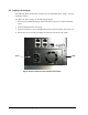
4. Remove all five drive trays from the system and look down at the controller board as
shown in figure A-10. Be sure to orient the rear of the system to your left as shown.
5. Locate the DIMM socket where you will be removing or installing the DIMM (see Figure A-
10, A-11 and A-12).
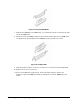
6. To remove a DIMM, carefully push the socket latches found on either side of the DIMM
socket, then pull the DIMM out of the socket (see Figure A-13). The latches hold the DIMM
tightly, so be careful not to break the socket.