xStack Storage TM D-Link xStack Storage iSCSI SAN Array Managed SAN Solution DSN-1100 Hardware Reference Guide Version 1.
© 2008 D-Link Networks, Inc. All Rights Reserved D-Link Systems, Inc. makes no warranty of any kind with regard to this material, including, but not limited to, the implied warranties of merchantability and fitness for a particular purpose. D-Link Systems, Inc. shall not be liable for errors contained herein or for incidental or consequential damages in connection with the furnishing, performance, or use of this material. This document contains proprietary information, which is protected by copyright.
Safety Information After completing the configuration of your DSN-1100 SAN array, please operate the unit with its front bezel door closed. This will help alleviate fire danger during normal SAN array operation. There is a danger of a new battery exploding if it is incorrectly installed. Replace the battery pack only with the same or equivalent type recommended by the manufacturer. Do not dispose of the battery along with household waste.
Document Revision Level iv Revision Date Version 1.
Preface This document is intended to assist users with installing the xStack Storage system from DLink. This document assumes that users are computer literate, familiar with Storage Array Products, and have a basic understanding of storage products and concepts. Typographic Conventions Notes Notes provide information that deserves special attention. They are preceded by: Cautions Cautions contain information which, if not followed, can cause damage to the xStack storage system.
Contact Information You can find software updates and user documentation on the D-Link website. D-Link provides free technical support for customers within the United States and within Canada for the duration of the warranty period on this product. U.S. and Canadian customers can contact D-Link Technical Support through our website, or by phone. Tech Support for customers within the United States: D-Link Technical Support over the Telephone Please see our support site for current number: http://support.
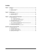
Contents Chapter 1 Introduction ..................................................................................................................................9 1.1 1.2 1.3 Chapter 2 DSN-1100 Layout .......................................................................................................................11 2.1 2.2 2.3 Chapter 3 Model .............................................................................................. 9 Benefits and Features ....................................
This Page Left Intentionally Blank viii Contents
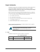
Chapter 1 Introduction The DSN-1100 storage system is an intelligent, high-performance multiple Gigabit Ethernet storage solution designed for small businesses that want to improve the reliability, availability, serviceability, and performance of their storage systems. It provides a range of benefits and features from its ability to use familiar, proven, and widespread networking technologies like IP and Ethernet for storage solutions.
1.2 1.
Chapter 2 DSN-1100 Layout This chapter describes the hardware components on the DSN-1100 storage system. The topics covered in this chapter are: Section 2.1, Front Panel Components Section 2.2, Inside Front Cover Section 2.
2.1 Front Panel Components The front of the DSN-1100 storage system has the following components: Power LED – shows the DSN-1100 power on status. (see Figure 2-1 and Table 2-1) Ready/Fault LED – shows whether the DSN-1100 is ready for operation or encountered a fault condition. (see Figure 2-1 and Table 2-1) Battery Status LED – shows the state of the internal cache memory battery.
Table 2-1. Front Panel LEDs LED Power Color Green Description ON = DSN-1100 is powered on. OFF = power is not being received. Ready/Fault Battery Status OFF Array is powered off or performing its Power On Self Test. Red ON = a fault has occurred. Green ON = normal operation. Green ON (Illuminated steadily) = Good battery present. ON (Blinking) = Good battery present. Battery-Backup State. OFF = Battery not installed or is less than 5.6V.
Drive Power LED Drive Activity and Fault LED Figure 2-2. Hard Drive Power and Activity LEDs Table 2-2. Hard Drive LEDs (for each drive 00 through 04) LED 14 Color Description Drive Power Blue ON Drive is powered and operational. Drive Activity and Fault Green Blinking Data being transmitted or received from corresponding SATA drive.
2.2 Inside Front Cover The front panel of the DSN-1100 storage system enclosure features a lockable front door which hides the following components: System power switch (see Figure 2-3 and Table 2-3). Five hot-swappable drive trays. (see Figure 2-3) Drive 00 Drive 01 Drive 02 Drive 03 Drive 04 Power Switch Figure 2-3. Front View with Cover Open Table 2-3. Inside Front Cover Switch Switch Power Description Applies power to the DSN-1100 storage system.
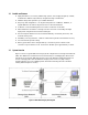
2.3 Rear Panel Components The rear of the DSN-1100 storage system enclosure has the following components: Data ports - four 1 GbE RJ-45 iSCSI data ports. Each iSCSI data port has port speed and port activity LEDs (see Figure 2-4, Figure 2-5 and Table 2-5). Management port (Mgmt 10/100) - one 10/100 RJ-45 management port is located to the right of the four iSCSI data ports. The management port has port speed and port activity LEDs (see Figure 2-4, Figure 2-5, and Table 2-6).
Figure 2-5. Close-Up View of the DSN-1100 Rear Panel Table 2-4. Rear Panel Switch Switch Description Reset Resets the DSN-1100 storage system. Please use the tip of a pen or a paper clip to reset the system. Note: This reboots the system and does not reset the unit to initial factory settings. Table 2-5. Data Port Speed and Port Activity LEDs LED Port Speed Color Yellow/Green Description Yellow = link is operating at 1 Gbps. Green = link is operating at 100 Mbps.
This Page Left Intentionally Blank 18 Chapter 2 DSN-1100 Layout
Chapter 3 Installing the DSN-1100 Storage System This chapter describes how to install the DSN-1100 storage system. The topics covered in this chapter are: Section 3.1, Site Considerations Section 3.2, Unpacking the DSN-1100 Storage System Section 3.3, Items Supplied by the User Section 3.4, Connecting to the iSCSI Data Ports Section 3.5, Connecting to the Management Port Section 3.6, Connecting the Power Cords Section 3.
3.1 Site Considerations The site where you install the DSN-1100 storage system can affect its performance. Therefore, choose a site that conforms to the requirements in the following sections. 3.1.1 General Considerations Observe the following considerations when selecting a location to install the DSN-1100 storage system. 3.1.2 The location should be fairly cool and dry for the acceptable temperature and humidity ranges.
3.2 Unpacking the DSN-1100 Storage System After receiving the DSN-1100 storage system, perform the following steps to ensure that it and other contents arrived safely. 1. Inspect the outer shipping container for any damage that may have occurred in shipping. Report any sign of damage to the appropriate shipping agency. 2. Remove the DSN-1100 storage system and cables from the shipping container. 3.
3.4 Connecting to the iSCSI Data Ports The following sections describe how to connect the DSN-1100 data ports. 3.4.1 Connecting to the DSN-1100 Host Network Connection Ports The DSN-1100 storage system has four RJ-45 data ports. These ports connect to your SAN using either a straight-through or cross-over RJ-45 Ethernet cable (the DSN-1100 storage system auto-senses the type of cable used). One cable is needed for each RJ-45 data port. 1.
3.6 Connecting the Power Cords The DSN-1100 storage system has a single power receptacle: 1. Plug the female end of the power cord into the 3-pronged power connectors on the back of the DSN-1100 storage system. Plug the other end of the power cord into a working AC outlet that is not controlled by a wall switch. 3.7 Powering-on the DSN-1100 Storage System To power-on the DSN-1100 storage system, press the power switch located inside the front cover.
This Page Left Intentionally Blank 24 Chapter 3 Installing the DSN-1100 Storage System
Appendix A Replacing and Upgrading FRUs This appendix describes how to replace or upgrade the Field Replaceable Units (FRUs) in your DSN-1100 storage system. FRUs that can be replaced or upgraded include: A.1 Battery Pack System and buffer memory SATA drives Fans Power supply Removing the Cover To remove the cover, use the following procedure. 1. Power down the DSN-1100 storage system and remove the power cord from the back panel. 2. Attach an ESD-preventive wrist strap. 3.
Screw Screw Screw Screw Screw Screw Figure A-1. Removing the Cover Slide Cover to Rear and Lift Up Figure A-2.
A.2 Installing the Battery Pack The xStack Storage Array accommodates a shrink-wrapped battery pack. Because write-back caching is always enabled, we recommend you have a battery to back up the buffer cache contents. The battery pack connects to the DSN-1100 controller board using a 3-pin locking connector at J11 (see Figure A-3 for detailed drawing of its location).
To install a battery in your xStack Storage SAN Array, follow these steps: 1. Hold the battery as shown to align the fastener strips. Make sure the battery cable and connector is located nearest to the battery socket J11 on the controller (see Figure A-4). Figure A-4 Aligning the Battery 2. Press the battery down firmly as shown in Figure A-5 until you feel it lock into place.
3. Carefully feed the battery’s connector up through the hole in the mounting plate as shown in Figure A-6. Do not damage the insulation on the wires. Figure A-6 Align the Battery Plug with Connector J11 4. Align the battery plug with connector J11 as shown in Figure A-7 and insert it fully into the socket.
5. The connector locked firmly into connector J11 as shown in Figure A-8. Figure A-8 Battery Plug Locked in Place 6. The installed battery is shown in Figure A-9.
A.3 Upgrading or Replacing Memory Your DSN-1100 storage system supports up to 1 GB of buffer(cache) memory and 512 MB of system memory using a total of two Dual In-line Memory Module (DIMM) sockets on the DSN1100 storage system Controller: One DIMM sockets (J14) is for buffer (cache) memory. One DIMM socket (J15) is for system memory. System Memory: The xStack Storage controller can address up to 512MB of system memory. Your controller comes standard with 256MB (1 x 256MB module).
Figure A-11 Buffer(Cache) Memory DIMM Socket Figure A-12 System Memory DIMM Socket 32 Appendix A Replacing and Upgrading FRUs
Table A-1. xStack Storage Array DIMM Specifications Requirement Description PC2700/DDR333 speed SDRAMs must be JEDEC compliant and DDR333 capable, with a CAS latency of 2.5. PC2100/DDR400 speed DIMMs can be used if they support a 2.5 CAS latency when operating at DDR333 speed. ECC DIMMs must be organized as x72 bits wide, allowing support for ECC. X8 RAMs DIMMs must use 8-bit wide DRAMs that can support data mask (DM) signals.
Figure A-13. Removing a DIMM Module 7. Hold the new DIMM above the DIMM socket, so its polarization notch is located at the right end of the DIMM socket. 8. Slowly insert the new DIMM by sliding the end with the metal fingers into the DIMM socket (see Figure A-14). Stop sliding when the DIMMM is securely seated in the socket. Figure A-14. Inserting a DIMM 9. Snap the latches into place. Do not use excessive force, because the socket might break. 10. Replace the cover (see section A.1). 11.
A.3 Installing or Replacing SATA Drive Removal of a populated drive/tray assembly can have unforeseen effects including the loss of all data in a volume. A drive can be part of a volume that may or may not be redundant. Before removing a drive from an operating xStack Storage Array, make sure it is the correct one. A.3.
A.3.2 Installing a Hard Drive in a Drive Tray Follow these steps to install a hard drive in a drive tray. 1. If there is one, remove the plastic air dam from the tray by squeezing the two levers together and lifting the piece out of the tray as shown in A-17. Figure A-17 Removing the Plastic Air Dam Piece 2. Your tray should now look like Figure A-18.
3. Place new hard drive in tray as shown in Figure A-19. Figure A-19 Place Hard Drive in Tray 4. Align the mounting holes and insert four mounting screws to hold the drive securely in the drive tray as shown in Figure A-.
5. Your hard drive is ready for installation. Proceed to A.3.3. A.3.3 Drive and Tray Installation A drive/tray assembly can be installed by inserting the drive/tray assembly into the open drive bay as shown in Figure A-21. Push the tray at the point indicated in Step 2 of Figure A-22 and push until it is seated firmly within the bay. As you press, you will see the tray handle begin to move inwards as the locking mechanism enters the locking slot.
Figure A-22 Press Here Until You See the Lever Move Inwards Figure A-23 Press Lever Inwards Until it Locks DSN-1100 Hardware Reference Guide 39
A.4 Replacing a Power Supply The DSN-1100 xStack Storage Array contains one user replaceable power supply. It can be replaced as follows. To replace the power supply, use the following procedure. 1. Power down the DSN-1100 storage system and remove the power cord from the back panel. 2. Attach an ESD-preventive wrist strap. 3. Open the enclosure to access the DSN-1100 storage system controller (see section A.1). 4. Remove the two screws shown in Figure A-24 found on the rear of the chassis.
5. Remove the two screws shown in Figure A-25 found on the bottom of the chassis. Screw Screw Figure A-25 Remove These Two Screws on the Bottom of the Chassis 6. Open the clip which holds the power supply wiring harness in place as shown in Figure A-26.
7. Remove the power supply harness connector as shown in Figure A-27. Figure A-27 Remove the Power Supply Harness Connector 8. Carefully slide the power supply out of the chassis as shown in Figure A-28. NOTE: Be sure not to damage the insulation on the wiring harness Figure A-28 Remove the Power Supply Harness Connector 9. To install a power supply, please reverse these steps.