xStack® DES-3200 Series Layer 2 Managed Fast Ethernet Switch Hardware Installation Guide 1
xStack® DES-3200 Series Layer 2 Managed Fast Ethernet Switch Hardware Installation Guide Information in this document is subject to change without notice. © 2012 D-Link Corporation. All rights reserved. Reproduction in any manner whatsoever without the written permission of D-Link Corporation is strictly forbidden. Trademarks used in this text: D-Link and the D-LINK logo are trademarks of D-Link Corporation; Microsoft and Windows are registered trademarks of Microsoft Corporation.
xStack® DES-3200 Series Layer 2 Managed Fast Ethernet Switch Hardware Installation Guide Table of Contents Intended Readers ................................................................................................................................................... iii Typographical Conventions...................................................................................................................................................... iii Notes, Notices, and Cautions...........................
xStack® DES-3200 Series Layer 2 Managed Fast Ethernet Switch Hardware Installation Guide Intended Readers Typographical Conventions Notes, Notices, and Cautions Safety Instructions Safety Cautions General Precautions for Rack-Mountable Products Protecting Against Electrostatic Discharge The DES-3200 Series Hardware Installation Guide contains detailed information about the hardware specifications of a Switch in this series.
xStack® DES-3200 Series Layer 2 Managed Fast Ethernet Switch Hardware Installation Guide Safety Cautions To reduce the risk of bodily injury, electrical shock, fire, or damage to the equipment, observe the following precautions. Observe and follow service markings. o Do not service any product except as explained in your system documentation. o Opening or removing covers that are marked with the triangular symbol with a lightning bolt may expose you to electrical shock.
xStack® DES-3200 Series Layer 2 Managed Fast Ethernet Switch Hardware Installation Guide o If the system has multiple sources of power, disconnect power from the system by unplugging all power cables from the power supplies. Move products with care; ensure that all casters and/or stabilizers are firmly connected to the system. Avoid sudden stops and uneven surfaces. General Precautions for Rack-Mountable Products Observe the following precautions for rack stability and safety.
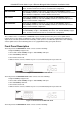
xStack® DES-3200 Series Layer 2 Ethernet Managed Switch Hardware Installation Guide Chapter 1 Introduction Switch Description Front Panel Description Rear Panel Description Side Panel Description Gigabit Combo Ports Switch Description The DES-3200 Series Hardware Installation Guide describes the hardware installation and specifications concerning the DES-3200 Series switches.
xStack® DES-3200 Series Layer 2 Ethernet Managed Switch Hardware Installation Guide 10/100/1000Mbps Copper / 100/1000Mbps SFP Ports, Two 10/100/1000Mbps Copper Ports, and One RJ-45 Console Port for out-of-band CLI configuration. DES-3200-28/ME Twenty-four 10/100Mbps Copper Ports, Two Combo 10/100/1000Mbps Copper / 100/1000Mbps SFP Ports, Two 100/1000Mbps SFP Ports, One RJ-45 Console Port for out-of-band CLI configuration, and One Alarm Connector Port.
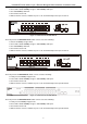
xStack® DES-3200 Series Layer 2 Ethernet Managed Switch Hardware Installation Guide Sixteen 10/100Mbps Copper Ports One Combo 10/100/1000Mbps Copper / 100/1000Mbps SFP port One 100/1000Mbps SFP Port One RJ-45 Console Port LEDs for Power, Console, Link/Act for port 1 to 16, and Link/Act/Speed for port 17 and 18 Figure 1-3.
xStack® DES-3200 Series Layer 2 Ethernet Managed Switch Hardware Installation Guide Figure 1-6. Front Panel of the DES-3200-26-DC The front panel of the DES-3200-28 switch consists out of the following: Twenty-four 10/100Mbps Copper Ports Two Combo 10/100/1000Mbps Copper / 100/1000Mbps SFP ports Two 100/1000Mbps SFP Ports One RJ-45 Console Port LEDs for Power, Console, Link/Act for port 1 to 24, and Link/Act/Speed for port 25 to 28 Figure 1-7.
xStack® DES-3200 Series Layer 2 Ethernet Managed Switch Hardware Installation Guide Figure 1-10. Front Panel of the DES-3200-28/ME The front panel of the DES-3200-52 switch consists out of the following: Forty-eight 10/100Mbps Copper Ports Two Combo 10/100/1000Mbps Copper / 100/1000Mbps SFP ports Two 100/1000Mbps SFP Ports One RJ-45 Console Port LEDs for Power, Console, Fan, Link/Act for port 1 to 48, and Link/Act/Speed for port 49 to 52 Figure 1-11.
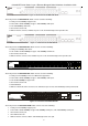
xStack® DES-3200 Series Layer 2 Ethernet Managed Switch Hardware Installation Guide LED Indicators The Switch supports LED indicators for Power, Console, Fan, and Link/Act or Link/Act/Speed for each port. The following shows the LED indicators for the DES-3200 Series along with an explanation of each indicator. Figure 1-14. LED Indicators on DES-3200-10 Figure 1-15. LED Indicators on DES-3200-10-DC Figure 1-16.
xStack® DES-3200 Series Layer 2 Ethernet Managed Switch Hardware Installation Guide Figure 1-17. LED Indicators on DES-3200-18-DC Figure 1-18. LED Indicators on DES-3200-26 Figure 1-19 LED Indicators on DES-3200-26-DC Figure 1-20.
xStack® DES-3200 Series Layer 2 Ethernet Managed Switch Hardware Installation Guide Figure 1-21. LED Indicators on DES-3200-28F Figure 1-22. LED Indicators on DES-3200-28P Figure 1-23. LED Indicators on DES-3200-28/ME Figure 1-24.
xStack® DES-3200 Series Layer 2 Ethernet Managed Switch Hardware Installation Guide Figure 1-25. LED Indicators on DES-3200-52-DC Figure 1-26. LED Indicators on DES-3200-52P Location LED Indicative Color Power Green Console Per Device Alarm (DES-320028/ME only) Status Description Solid Light Power on. Light off Power off. Solid Light Console on. Blinking POST is in progress. Light off Console off. Solid Light Attached device failure is detected.
xStack® DES-3200 Series Layer 2 Ethernet Managed Switch Hardware Installation Guide Solid Green LED Per 10/100/1000Mbps Copper Port When there is a secure 1000Mbps Ethernet connection (or link) at any of the ports. Blinking Green When there is reception or transmission (i.e. Activity—Act) of data occurring at a 1000Mbps Ethernet connected port. Link/Act/Speed Green/Amber Solid Amber When there is a secure 10/100Mbps Ethernet connection (or link) at any of the ports.
xStack® DES-3200 Series Layer 2 Ethernet Managed Switch Hardware Installation Guide Rear Panel Description The rear panel of the Switch contains an AC or DC power connector. The AC power connector is a standard threepronged connector that supports the power cord. Plug-in the female connector of the provided power cord into this socket, and the male side of the cord into a power outlet. The Switch automatically adjusts its power setting to any supply voltage in the range from 100 to 240 VAC at 50 to 60 Hz.
xStack® DES-3200 Series Layer 2 Ethernet Managed Switch Hardware Installation Guide Figure 1-33. Rear panel view of the DES-3200-28 Figure 1-34. Rear panel view of the DES-3200-28F Figure 1-35. Rear panel view of the DES-3200-28P Figure 1-36. Rear panel view of the DES-3200-28/ME Figure 1-37. Rear panel view of the DES-3200-52 -48V 1.1AMAX - 48V Figure 1-38. Rear panel view of the DES-3200-52-DC Figure 1-39.
xStack® DES-3200 Series Layer 2 Ethernet Managed Switch Hardware Installation Guide Side Panel Description The left- and right-hand panels of the Switch have heat vents to dissipate heat. Do not block these openings, and leave at least 6 inches of space at the rear and sides of the Switch for proper ventilation. Be reminded that without proper heat dissipation and air circulation, system components might overheat, which could lead to system failure Figure 1-40. Side panels of the DES-3200-10 Figure 1-41.
xStack® DES-3200 Series Layer 2 Ethernet Managed Switch Hardware Installation Guide Figure 1-43. Side panels of the DES-3200-18-DC Figure 1-44. Side panels of the DES-3200-26 Figure 1-45. Side panels of the DES-3200-26-DC Figure 1-46.
xStack® DES-3200 Series Layer 2 Ethernet Managed Switch Hardware Installation Guide Figure 1-47. Side panels of the DES-3200-28F Figure 1-48. Side panels of the DES-3200-28P Figure 1-49. Side panels of the DES-3200-28/ME Figure 1-50.
xStack® DES-3200 Series Layer 2 Ethernet Managed Switch Hardware Installation Guide Figure 1-51. Side panels of the DES-3200-52-DC Figure 1-52. Side panels of the DES-3200-52P Gigabit Combo Ports The DES-3200 Series features either two or four Gigabit Ethernet Combo ports. These ports are 1000BASE-T copper ports (optional) and Small Form Factor Portable (SFP) ports (optional). See the diagram below to view the two SFP port modules being plugged into the Switch.
xStack® DES-3200 Series Layer 2 Ethernet Managed Switch Hardware Installation Guide Figure 1- 27. Installing the SFP Module The Switch is equipped with SFP ports, which are to be used with fiber-optical transceiver cabling in order to uplink various other networking devices for a gigabit link that may span great distances. For a full list of supported SFP transceivers, for this switch series, refer to the Appendix A.
xStack® DES-3200 Series Layer 2 Ethernet Managed Switch Hardware Installation Guide Chapter 2 Installation Package Contents Before You Connect to the Network Installing the Switch without the Rack Installing the Switch in a Rack Mounting the Switch in a Standard 19" Rack Power on AC Power Connecting DC Power Package Contents Open the shipping carton of the Switch and carefully unpack its contents.
xStack® DES-3200 Series Layer 2 Ethernet Managed Switch Hardware Installation Guide Installing the Switch without the Rack When installing the Switch on a desktop or shelf, the rubber feet included with the Switch should first be attached. Attach these cushioning feet on the bottom at each corner of the device. Allow enough ventilation space between the Switch and any other objects in the vicinity. Figure 2-1.
xStack® DES-3200 Series Layer 2 Ethernet Managed Switch Hardware Installation Guide Mounting the Switch in a Standard 19" Rack CAUTION: Installing systems in a rack without the front and side stabilizers installed could cause the rack to tip over, potentially resulting in bodily injury under certain circumstances. Therefore, always install the stabilizers before installing components in the rack.
xStack® DES-3200 Series Layer 2 Ethernet Managed Switch Hardware Installation Guide Figure 2-4. Close-up view of Power Receptacle 1. The DC power supply has a three-terminal wiring block consisting of a positive (+), a negative (-) and a safety ground terminal. 2. Firmly attach the DC power to the negative and positive contacts on the wiring assembly. a. The negative pole (-) connects to the -48V contact. b. The positive pole (+) connects to the -48V Return contact. c.
xStack® DES-3200 Series Layer 2 Ethernet Managed Switch Hardware Installation Guide Alarm Connector Port Contact Description 1 Output. Normal Closed Pin. (42VAC or 60VDC) 2 Output. Common Pin. (42VAC or 60VDC) 3 Output. Normal Open Pin. (42VAC or 60VDC) 4 Input 2. 5 Input 2. 6 Input 1. 7 Input 1. Connect the alarm input pins to alarm output terminals.
xStack® DES-3200 Series Layer 2 Ethernet Managed Switch Hardware Installation Guide Chapter 3 Connecting the Switch Switch to End Node Switch to Hub or Switch NOTE: All 10/100/1000Mbps NWay Ethernet ports can support both MDI-II and MDI-X connections. Switch to End Node End node is a generic name for edge networking devices that are connected to the Switch. Typical examples of end nodes are Personal Computers (PCs), Notebooks, Access Points, Print Servers, VoIP Phones and more.
xStack® DES-3200 Series Layer 2 Ethernet Managed Switch Hardware Installation Guide Switch to Hub or Switch These connections can be accomplished in a number of ways using a normal cable. A 10BASE-T hub or switch can be connected to the Switch via a twisted-pair Category 3, 4, 5 or 5e UTP/STP cable. A 100BASE-TX hub or switch can be connected to the Switch via a twisted-pair Category 5 or 5e UTP/STP cable.
xStack® DES-3200 Series Layer 2 Ethernet Managed Switch Hardware Installation Guide Chapter 4 Introduction to Switch Management Management Options Web-based Management Interface SNMP-Based Management Connecting the Console Port First Time Connecting to the Switch Password Protection SNMP Settings IP Address Assignment Management Options This system may be managed out-of-band through the console port on the front panel or in-band using Telnet.
xStack® DES-3200 Series Layer 2 Ethernet Managed Switch Hardware Installation Guide 7. After you have correctly set up the terminal, plug the power cable into the power receptacle on the back of the Switch. The boot sequence appears in the terminal. 8. After the boot sequence completes, the console login screen displays. 9. If you have not logged into the command line interface (CLI) program, press the Enter key at the User name and password prompts.
xStack® DES-3200 Series Layer 2 Ethernet Managed Switch Hardware Installation Guide DES-3200-28P Fast Ethernet Switch Command Line Interface Firmware: Build 4.04.003 Copyright(C) 2012 D-Link Corporation. All rights reserved. UserName: PassWord: DES-3200-28P:admin# Figure 4-2. Command Prompt NOTE: The first user automatically gets Administrator level privileges. It is recommended to create at least one Admin-level user account for the Switch.
xStack® DES-3200 Series Layer 2 Ethernet Managed Switch Hardware Installation Guide NOTICE: In case of lost passwords or password corruption, please refer to the section titled “Password Recovery Procedure” in Appendix B of the CLI Reference Guide” which will guide you through the steps necessary to resolve this issue. SNMP Settings Simple Network Management Protocol (SNMP) is an OSI Layer 7 (Application Layer) designed specifically for managing and monitoring network devices.
xStack® DES-3200 Series Layer 2 Ethernet Managed Switch Hardware Installation Guide own proprietary enterprise MIB as an extended Management Information Base. Specifying the MIB Object Identifier may also retrieve the proprietary MIB. MIB values can be either read-only or read-write. IP Address Assignment Each Switch must be assigned its own IP Address, which is used for communication with an SNMP network manager or other TCP/IP application (for example BOOTP, TFTP). The Switch's default IP address is 10.
xStack® DES-3200 Series Layer 2 Ethernet Managed Switch Hardware Installation Guide Alternatively, you can enter config ipif System ipaddress xxx.xxx.xxx.xxx/z. Where the x's represent the IP address to be assigned to the IP interface named System and the z represents the corresponding number of subnets in CIDR notation.
xStack® DES-3200 Series Layer 2 Ethernet Managed Switch Hardware Installation Guide Chapter 5 Web-based Switch Configuration Introduction Login to Web manager Web-Based User Interface Introduction All software functions of the Switch can be managed, configured and monitored via the embedded web-based (HTML) interface. The Switch can be managed from remote stations anywhere on the network through a standard browser such as Firefox or Microsoft Internet Explorer.
xStack® DES-3200 Series Layer 2 Ethernet Managed Switch Hardware Installation Guide Web-based User Interface The user interface provides access to various Switch configuration and management windows, allows you to view performance statistics, and permits you to graphically monitor the system status. Areas of the User Interface The figure below shows the user interface. The user interface is divided into three distinct areas as described in the table. Area 2 Area 1 Area 3 Figure 5-2.
xStack® DES-3200 Series Layer 2 Ethernet Managed Switch Hardware Installation Guide Web Pages When you connect to the management mode of the Switch with a Web browser, a login window is displayed. Enter a user name and password to access the Switch's management mode. When connecting to the management mode of the Switch with a web browser, a login screen is displayed. Enter a user name and password to access the Switch's management mode.
xStack® DES-3200 Series Layer 2 Ethernet Managed Switch Hardware Installation Guide Appendix A – Technical Specifications General Protocols IEEE 802.3 10BASE-T Ethernet IEEE 802.3u 100BASE-TX Fast Ethernet IEEE 802.3ab 1000BASE-T Gigabit Ethernet IEEE 802.3z 1000BASE-X (SFP “Mini GBIC”) IEEE 802.1D Spanning Tree IEEE 802.1w Rapid Spanning Tree Protocol IEEE 802.1s Multiple Spanning Tree Protocol IEEE 802.1Q VLAN IEEE 802.1p Priority Queues IEEE 802.1X Port Based Network Access Control IEEE 802.
xStack® DES-3200 Series Layer 2 Ethernet Managed Switch Hardware Installation Guide DES-3200-18-DC - Sixteen 10/100Mbps Copper Ports, One 100/1000Mbps SFP Port, One Combo 10/100/1000Mbps Copper / 100/1000Mbps SFP Port. DES-3200-26 - Twenty-four 10/100Mbps Copper Ports, Two Combo 10/100/1000Mbps Copper / 100/1000Mbps SFP Ports. DES-3200-26-DC - Twenty-four 10/100Mbps Copper Ports, Two Combo 10/100/1000Mbps Copper / 100/1000Mbps SFP Ports.
xStack® DES-3200 Series Layer 2 Ethernet Managed Switch Hardware Installation Guide DES-3200-52: One fan DES-3200-52-DC: One fan DES-3200-52P: Four Fans The other switches in this series are Fanless. Operating Temperature -5 - 50°C Storage Temperature -40 - 70°C MTBF DES-3200-10: 738,787.9883 hours DES-3200-10-DC: 931,568.
xStack® DES-3200 Series Layer 2 Ethernet Managed Switch Hardware Installation Guide Performance Transmission Method Store-and-forward Packet Buffer 1.5MB per device Packet Filtering/ Forwarding Rate 14,881 pps (10M port) 148,810 pps (100M port) 1,488,100 pps (1Gbps port) MAC Address Learning Automatic update. Supports 16K MAC address Priority Queues 8 Priority Queues per port Forwarding Table Age Time Max age: 10-1000000 seconds. Default = 300.
xStack® DES-3200 Series Layer 2 Ethernet Managed Switch Hardware Installation Guide Blinking Amber When there is reception or transmission (i.e. Activity—Act) of data occurring at a 10/100Mbps Ethernet connected port. LED Per 10/100Mbps Port in PoE PoE Mode (DES3200-28P/52P Only) LED Per 100Mbps SFP Port (DES3200-28F Only) Link/Act LED Per 100/1000Mbps SFP Link/Act/Speed Port Green Light off No link. Solid Green Power feeding. Blinking Green Error Condition Green Light off No power feeding.
xStack® DES-3200 Series Layer 2 Ethernet Managed Switch Hardware Installation Guide 100Mbps SFP Ports (DES-3200-28F Only) Compliant to the following standards: IEEE 802.3 compliance IEEE 802.3u compliance Support Full-Duplex operations IEEE 802.
xStack® DES-3200 Series Layer 2 Ethernet Managed Switch Hardware Installation Guide Appendix B – Cables and Connectors Ethernet Cable When connecting the Switch to another switch, a bridge or hub, a normal cable is necessary. Please review these products for matching cable pin assignment. The following diagrams and tables show the standard RJ-45 receptacle/connector and their pin assignments. Figure B- 1.
xStack® DES-3200 Series Layer 2 Ethernet Managed Switch Hardware Installation Guide Console Cable When connecting the Switch a PC, a Console cable is necessary. The following diagrams and tables show the standard Console-to-DJ-45 receptacle/connector and their pin assignments. Figure B- 2.
xStack® DES-3200 Series Layer 2 Ethernet Managed Switch Hardware Installation Guide Appendix C – Module Specs and Cable Lengths Use the following table to as a guide for the module specs and maximum cable lengths.
Subject to the terms and conditions set forth herein, D-Link Systems, Inc. (“D-Link”) provides this Limited Warranty: • • Only to the person or entity that originally purchased the product from D-Link or its authorized reseller or distributor, and Only for products purchased and delivered within the fifty states of the United States, the District of Columbia, U.S. Possessions or Protectorates, U.S. Military Installations, or addresses with an APO or FPO.
Limitation of Liability: TO THE MAXIMUM EXTENT PERMITTED BY LAW, D-LINK IS NOT LIABLE UNDER ANY CONTRACT, NEGLIGENCE, STRICT LIABILITY OR OTHER LEGAL OR EQUITABLE THEORY FOR ANY LOSS OF USE OF THE PRODUCT, INCONVENIENCE OR DAMAGES OF ANY CHARACTER, WHETHER DIRECT, SPECIAL, INCIDENTAL OR CONSEQUENTIAL (INCLUDING, BUT NOT LIMITED TO, DAMAGES FOR LOSS OF GOODWILL, LOSS OF REVENUE OR PROFIT, WORK STOPPAGE, COMPUTER FAILURE OR MALFUNCTION, FAILURE OF OTHER EQUIPMENT OR COMPUTER PROGRAMS TO WHICH D-LINK’S PRODUCT
Product Registration Register your D-Link product online at http://support.dlink.com/register/ Product registration is entirely voluntary and failure to complete or return this form will not diminish your warranty rights.
Tech Support Technical Support You can find software updates and user documentation on the DLink website. D-Link provides free technical support for customers within the United States and within Canada for the duration of the service period, and warranty confirmation service, during the warranty period on this product. U.S. and Canadian customers can contact D-Link technical support through our website, or by phone.
Technical Support United Kingdom (Mon-Fri) Home Wireless/Broadband 0871 873 3000 (9.00am–06.00pm, Sat 10.00am-02.00pm) Managed, Smart, & Wireless Switches, or Firewalls 0871 873 0909 (09.00am – 05.30pm) (BT 10ppm, other carriers may vary.) Ireland (Mon-Fri) All Products 1890 886 899 (09.00am-06.00pm, Sat 10.00am-02.00pm) €0.05ppm peak, €0.045ppm off peak Times Internet http://dlink.com Technische Unterstützung Deutschland: Österreich: Schweiz: Web: http://dlink.
Assistance technique Assistance technique D-Link sur internet : http://dlink.com Assistance technique D-Link par téléphone : 01 76 54 84 17 Du lundi au vendredi de 9h à 19h (hors jours fériés) Asistencia Técnica Asistencia Técnica Telefónica de D-Link: +34 902 30 45 45 0,067 €/min De Lunes a Viernes de 9:00 a 19:00 http://dlink.com Supporto tecnico Supporto Tecnico dal lunedì al venerdì dalle ore 9.00 alle ore 19.00 con orario continuato Telefono: 02 87366396 http://dlink.
Pomoc techniczna Telefoniczna pomoc techniczna firmy D-Link: 0 801 022 021 Pomoc techniczna firmy D-Link świadczona przez Internet: http://dlink.com Technická podpora Web: http://dlink.com E-mail: support@dlink.cz Telefon ČR: +420 211 151 640 nebo SK: +421 (0)692 147 110 Telefonická podpora je v provozu: PO - PÁ od 09:00 do 17:00 Volání je zpoplatněno dle příslušných tarifů Vašeho operátora. Technikai Támogatás Tel. : 06 1 461-3001 Fax : 06 1 461-3004 Land Line 14,99 HUG/min - Mobile 49.
Teknistä tukea asiakkaille Suomessa: Internetin kautta : http://dlink.com Arkisin klo. 09:00 - 18: 00 Numerosta : 0200-555 57 Teknisk Support D-Link Teknisk Support via Internet: http://dlink.com D-Link Teknisk Support via telefon: 0770-33 00 35 Vardagar 08:00 - 17:00 Assistência Técnica Assistência Técnica da D-Link na Internet: http://dlink.com e-mail: soporte@dlink.es Τεχνική Υποστήριξη D-Link Hellas Support Center http://dlink.com Καλύμνου 12, 112 51, Αθήνα Τηλ. 213 0020353 (Δευτέρα - Παρασκευή, 09.
Tehnička podrška Hvala vam na odabiru D-Link proizvoda. Za dodatne informacije, podršku i upute za korištenje uređaja, molimo vas da posjetite D-Link internetsku stranicu na www.dlink.eu http://dlink.com Tehnična podpora Zahvaljujemo se vam, ker ste izbrali D-Link proizvod. Za vse nadaljnje informacije, podporo ter navodila za uporabo prosimo obiščite D-Link - ovo spletno stran www.dlink.eu http://dlink.com Suport tehnic Vă mulţumim pentru alegerea produselor D-Link.
Technical Support You can find software updates and user documentation on the D-Link website. Tech Support for customers in Australia: Tel: 1300-766-868 24/7 Technical Support Web: http://www.dlink.com.au E-mail: support@dlink.com.au India: Tel: +91-22-27626600 Toll Free 1800-22-8998 Web: www.dlink.co.in E-Mail: helpdesk@dlink.co.in Singapore, Thailand, Indonesia, Malaysia, Philippines, Vietnam: Singapore - www.dlink.com.sg Thailand - www.dlink.co.th Indonesia - www.dlink.co.id Malaysia - www.dlink.com.
Technical Support You can find software updates and user documentation on the D-Link website. Tech Support for customers in Iran Unit 5, 5th Floor, No. 20, 17th Alley , Bokharest St. , Argentine Sq. , Tehran IRAN Postal Code : 1513833817 Tel: +98-21-88880918,19 +98-21-88706653,54 General Inquiries: info.ir@dlink-me.com Tech Support: support.ir@dlink-me.com Morocco M.I.T.C Route de Nouaceur angle RS et CT 1029 Bureau N° 312 ET 337 Casablanca , Maroc Phone : +212 663 72 73 24 Email: support.na@dlink-me.
Техническая поддержка Обновления программного обеспечения и документация доступны на Интернет-сайте D-Link. D-Link предоставляет бесплатную поддержку для клиентов в течение гарантийного срока. Клиенты могут обратиться в группу технической поддержки D-Link по телефону или через Интернет. Техническая поддержка D-Link: 8-800-700-5465 Техническая поддержка через Интернет: http://www.dlink.ru e-mail: support@dlink.ru Офисы Россия 129626 г. Москва Графский пер., 14 Тел.: +7 (495) 744-0099 Украина, 04080 г.
SOPORTE TÉCNICO Usted puede encontrar actualizaciones de softwares o firmwares y documentación para usuarios a través de nuestro sitio www.dlinkla.
Suporte Técnico Caso tenha dúvidas na instalação do produto, entre em contato com o Suporte Técnico D-Link. Acesse o site: www.dlink.com.
D-Link 友訊科技 台灣分公司 技術支援資訊 如果您還有任何本使用手冊無法協助您解決的產品相關問題,台灣 地區用戶可以透過我們的網站、電子郵件或電話等方式與D-Link台灣 地區技術支援工程師聯絡。 D-Link 免付費技術諮詢專線 0800-002-615 服務時間:週一至週五,早上9:00到晚上9:00 (不含周六、日及國定假日) 網 站:http://www.dlink.com.tw 電子郵件:dssqa_service@dlink.com.tw 如果您是台灣地區以外的用戶,請參考D-Link網站全球各地 分公司的聯絡資訊以取得相關支援服務。 產品保固期限、台灣區維修據點查詢,請參考以下網頁說明: http://www.dlink.com.
Dukungan Teknis Update perangkat lunak dan dokumentasi pengguna dapat diperoleh pada situs web D-Link. Dukungan Teknis untuk pelanggan: Dukungan Teknis D-Link melalui telepon: Tel: +62-21-5731610 Dukungan Teknis D-Link melalui Internet: Email : support@dlink.co.id Website : http://support.dlink.co.
Technical Support この度は弊社製品をお買い上げいただき、誠にありがとうご ざいます。 下記弊社 Web サイトからユーザ登録及び新製品登録を 行っていただき、ダウンロードサービスにて サポート情報、ファームウェア、ユーザマニュアルを ダウンロードすることができます。 ディーリンクジャパン Web サイト URL:http://www.dlink-jp.
技术支持 办公地址:北京市东城区北三环东路 36 号 环球贸易中心 B 座 26F 02-05 室 邮编: 100013 技术支持中心电话:400-629-6688 / 800-829-6688 技术支持中心传真:(028) 87300889 各地维修中心地址请登陆官方网站查询 网址:http://www.dlink.com.cn 800电话工作时间:工作日9:00-19:00;节假日9:00-18:00.
Registration Card All Countries and Regions Excluding USA Print, type or use block letters. Your name: Mr./Ms_____________________________________________________________________________ Organization: ________________________________________________ Dept.