Table of Contents Table of Contents Product Overview......................................................... 4 Package Contents.................................................... 4 System Requirements.............................................. 4 Introduction............................................................... 5 Features.................................................................... 6 Hardware Overview.................................................. 7 LEDs.............................
Table of Contents Networking Basics................................................... 141 Check your IP Address......................................... 141 Statically Assign an IP Address............................ 142 Technical Specifications.......................................... 143 Contacting Technical Support................................. 145 Warranty.................................................................... 146 Registration...........................................................
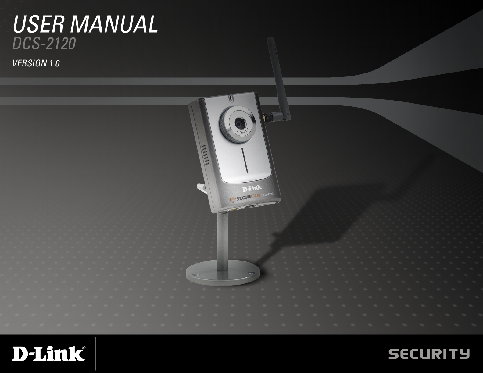
Section 1 - Product Overview Product Overview Package Contents • D-Link DCS-2120 Wireless Internet Camera with 3G Mobile Video Support • CAT5 Ethernet Cable • Power Adapter • Antenna • Manual and Software on CD • Quick Install Guide • Camera Stand Note: Using a power supply with a different voltage than the one included with your product will cause damage and void the warranty for this product. If any of the above items are missing, please contact your reseller.
Section 1 - Product Overview Introduction The D-Link SECURICAM Network DCS-2120 Wireless Internet Camera is a powerful surveillance system that connects wirelessly to your 802.11b/g network. The DCS-2120 features enhanced 802.11b/g and connects wirelessly at a rate of up to 54Mbps1 (Megabits per second).
Section 1 - Product Overview Features • 3G Compatibility: Offers customers the ability to view live video streams from a compatible 3G cell phone. The live camera feed can be pulled from a 3G cellular network by using a compatible cell phone with a 3G video player.
Section 1 - Product Overview Hardware Overview Antenna Connector One antenna is included with the DCS-2120. It is fastened onto the antenna connector on the side panel to provide a connection with a wireless network. DC Power Connector The DC Power input connector is labeled DC 5V with a single jack socket to supply power to the DCS-2120. Ethernet Cable Connector The DCS-2120 features an RJ-45 connector for connections to 10Base-T Ethernet cabling or 100Base-TX Fast Ethernet cabling.
Section 1 - Product Overview LEDs Power LED The power LED is positioned in the center of the camera below the Internet Camera Lens. As soon as the power adapter is connected to the camera, the power LED will flash red and blue several times, indicating that the DCS-2120 is conducting a self-test. Upon passing the self-test, the LED will turn blue, indicating a good connection to an Ethernet or wireless connection. A red LED indicates that no connection has been made.
Section 1 - Product Overview Hardware Installation Connect an Ethernet cable to the Ethernet connector located on the Internet Camera’s bottom panel and attach it to the network. Note: It is required that an Ethernet cable is used during initial setup. Once your wireless configuration is set, you may disconnect the Ethernet cable. Attach the external power supply to the DC power input connector located on the Internet Camera’s bottom panel (labeled 5VDC) and connect it to your wall outlet.
Section 2 - Installation Wireless Installation Considerations The D-Link wireless internet camera lets you access your network using a wireless connection from virtually anywhere within the operating range of your wireless network. Keep in mind, however, that the number, thickness and location of walls, ceilings, or other objects that the wireless signals must pass through, may limit the range.
Section 2 - Installation Software Installation Turn on the computer and Insert the D-Link DCS-2120 Driver CD in the CD-ROM drive. The step-by-step instructions that follow are shown in Windows® XP. The steps and screens are similar for the other Windows® operating systems. Click Installation Wizard If the CD Autorun function does not automatically start on your computer, click Windows® Start > Run. In the Run command box type “D:\DCS2120.exe”, where D: represents the drive letter of your CD-ROM.
Section 2 - Installation Please wait while the InstallShield Wizard prepares to install.
Section 2 - Installation The InstallShield will install the software in the following folder. To install the software into a different folder, click Browse and select another folder. Click Next Select the Program folder that Setup will add program icons to. You may type a new folder name, or select one from the existing folders list.
Section 2 - Installation Please wait while the Installation Wizard is installed. Installation is now complete.
Section 2 - Installation To access the Installation Wizard screen, click on the Installation Wizard Icon on your desktop. The Installation Wizard screen will appear and show the MAC address and IP address of your DCS-2120. If you have a DHCP* server on your network, there will be a valid IP Address displayed here, indicated by a “Yes” under the assigned column. *A DHCP server is a device that supplies IP Addresses to its clients that are on the same network.
Section 3 - Configuration Configuration This section will show you how to configure your new D-Link wireless internet camera using the D-Link Installation Wizard.
Section 3 - Configuration Setup On the initial Setup Screen you can configure System and Date/Time settings for each camera. Click Next to configure Network settings for the camera.
Section 3 - Configuration Network Settings Users can configure the Network Settings for the camera by entering the IP address, Subnet mask, Default router IP, Primary DNS, and Secondary DNS. The option to reset IP address at boot is automatically selected. If you would like to keep your IP address settings, make sure to uncheck this box. Click Next Note: These settings can also be configured on the Advanced > Network page when configuring the camera via a Web Browser.
Section 3 - Configuration Wireless Network Settings Users can configure the Wireless Network Settings for the camera, by entering the SSID and selecting the Wireless Mode, Channel, TX Rate, and Preamble. Click Next Note: Check the Data Encryption box to enable data encryption and configure the settings. These settings are explained and can also be configured on the Advanced > Network screen (page 32) when configuring the camera via a Web Browser.
Section 3 - Configuration Click Apply to save the configured settings. Users can click Previous to modify changes.
Section 3 - Configuration Upgrade The upgrade window allows users to upload the firmware. If the firmware is older than the current one on the camera, a message will appear indicating this, prompting the user to confirm the uploading.
Section 3 - Configuration Enabling UPnP for Windows® XP UPnP (Universal Plug and Play) is a networking architecture that provides compatibility among networking equipment, software, and peripherals. The DCS-2120 is an UPnP enabled Internet camera. If your operating system is UPnP enabled, the device will be easier to configure. If you do not want to use the UPnP functionality, it can be disabled by unchecking the Enabled UPnP checkbox in the Advanced > Network page (see page 33).
Section 3 - Configuration Click Add/Remove Windows Components The following screen will appear. Select Networking Services. Click Details Select Universal Plug and Play.
Section 3 - Configuration Click Next Please wait while Setup configures the components.
Section 3 - Configuration To view your DCS-2120 Internet Camera in an Internet browser, go to your Desktop and click My Network Places. Click DCS-2120 (192.168.0.120).
Section 3 - Configuration After you click on the DCS-2120-120 icon, your Internet browser will automatically be opened to the IP Address of the DCS-2120, in this example it is: http://192.168.0.120. Your DCS-2120 may have a different IP Address.
Section 3 - Configuration Testing the DCS-2120 Open your Internet browser and type in the IP address of the DCS-2120. In this example, the address is: http://192.168.0.120 (your DCS-2120 may have a different IP address based on what you used in the Installation Wizard program). The window in the center of your browser is the camera image window. You should now see a video image and hear the audio over your computer speakers from the DCS-2120.
Section 3 - Configuration Viewing Your DCS-2120 After all the router settings have been entered correctly, a PC user inside or outside your network will have access to the camera through the Internet Explorer Web browser. To access the camera from the Internet, type the IP Address of the router given to you by your ISP, followed by a colon, and the port number that you gave your camera (e.g., http://70.42.15.9:83).
Section 3 - Configuration Using the DCS-2120 with an Internet Browser Open your Internet Explorer Web browser and enter the IP address for your Internet Camera (http://192.168.0.120). In the example, this address is 192.168.0.120. Your address may differ. If a window appears asking to install a Verisign certificate for authentication Click Yes. This allows the proprietary MPEG 4 video stream to be recognized by Internet Explorer.
Section 3 - Configuration Home Page Screen The image from the DCS-2120 should be visible from the Home page on your computer monitor. Snapshot: Click on the Snapshot button to capture a snapshot image. The image will pop up in a new window. This image can be saved into the local hard drive. Connection Type: Click on the Connection Type button to change settings related to the camera connection.
Section 3 - Configuration Connection Type Media Option: Allows a user to disable audio when viewing video. Protocol Option: The UDP Protocol should be chosen for most users. Generally, the client computer will automatically try these protocols in the following order, UDP -> TCP. After the client connects to the DCS-2120 successfully, the working protocol will be displayed in Protocol Option. The chosen protocol will be saved in the user’s PC and used for the next connection.
Section 3 - Configuration DCS-2120 Configuration Advanced There are 5 tabs across the top of the Configuration screen. From each tab, different elements of the DCS-2120 can be configured. The Advanced tab provides the following configuration options: Network, Mail & FTP, DDNS, Access List, Audio/Video, Image Setting, and Motion Detection.
Section 3 - Configuration Network Reset IP Address at next boot: DCS-2120 will request a new IP address from the DHCP server everytime it restarts. Once the DCS-2120 is configured, this box should be unchecked at all times. If the box has been checked and the connection is lost, run the Installation Wizard to find the camera’s IP address. IP address: Necessary for network identification. Subnet mask: Used to determine if the destination is in the same subnet. The default value is “255.255.255.0.
Section 3 - Configuration Access name: This option allows the user to specify the file name for RTSP streaming. RTSP port: This option allows the user to set a port other than the default UDP port 554. SSID: (Service Set Identifier) is a name that identifies a wireless network. Access Points and wireless clients attempting to connect to a specific WLAN (Wireless Local Area Network) must use the same SSID. The default setting is dlink.
Section 3 - Configuration Key format: Select an ASCII or HEX (hexadecimal) key format. Key index: You can create up to 4 different security keys. Pre-shared key: The Key allows the camera to connect to other devices by using WPA-PSK encryption. Pre-shared key must be 8-63 characters or 64 hex characters.
Section 3 - Configuration Mail & FTP Sender email address: The sender’s email address that appears in the mail alert. 1st SMTP (mail) server: The domain name or IP address of external mail server. 1st SMTP account name: The user name used to log into your e-mail account (e.g. jdoe or jdoe@yourisp.com). 1st SMTP password: The password used to log into your e-mail account. The password will appear as dots instead of entered characters.
Section 3 - Configuration 1st FTP server: The host name of the FTP server. 1st FTP server port: The port of the FTP server. Usually the port number of FTP server is 21. It depends on the FTP server’s setup. 1st FTP user name: The account name to access the FTP server. 1st FTP password: The password that was setup with the account to access the FTP server. 1st FTP remote folder: The directory that the images will be uploaded into (For example, \pub\images).
Section 3 - Configuration DDNS Click the DDNS button from the Configuration screen to access DDNS settings. Dynamic DNS (DDNS): Dynamic DNS (Domain Name Service) is a method of keeping a domain name linked to a changing (dynamic) IP address. With most Cable and DSL connections, you are assigned a dynamic IP address and that address is used only for the duration of that specific connection.
Section 3 - Configuration Access List Click the Access List button from the Configuration screen to access Access List settings. Allow List Start IP Address: The starting IP Address of the devices (such as a computer) that has the permission to access the video of the camera. Allow List End IP Address: The ending IP Address of the devices (such as a computer) that has the permission to access the video of the camera. Delete Allow List: Remove the customized setting from the Allow List.
Section 3 - Configuration Audio/Video Click the Audio/Video button from the Configuration screen to access audio and video settings that affect how the audio and video appears. Configure for computer viewing: Select this option to switch to computer viewing. Configure for mobile viewing: Select this option to switch to mobile device viewing. The frame size will change to 176x144, 5 FPS and Video Quality: 40kps Color: Select the option for color or monochrome video display.
Section 3 - Configuration reduced in order to send maximum frames with limited bandwidth, especially when images change drastically. For higher video detail regardless of the bandwidth selection, select Fixed quality and select a video quality level. This setting will utilize more bandwidth to send the maximum frames when images change drastically. Video quality control: These settings are to optimize your camera performance with your available bandwidth.
Section 3 - Configuration Recommendations for Setting Video for the Best Performance: “Best performance” means the image refresh rate should be the fastest possible and the video quality should be the best possible at the lowest network bandwidth possible. Three factors, Maximum frame rate, Fix bit rate, and Fix quality in the Video Configuration page, are related to performance.
Section 3 - Configuration Image Setting Click the Image Setting button from the Configuration screen to access additional settings that affect how the video image appears. From this screen you can fine tune the video image. Image Brightness, Contrast, Saturation and Hue are all adjustable in the same manner. For each video compensation, you can set from among eleven levels ranged from -5 to +5. The default setting is zero for each adjustment.
Section 3 - Configuration Motion Detection Click the Motion Detection button from the Configuration screen to enable the motion detection function of the DCS-2120 Internet Camera. Enable motion detection: Check this option to turn on the motion detection. New: Adds new windows that monitor specific area of the image window. Up to 3 motion detection windows can be added. Save: Saves the new windows settings. Window Name: The name of the motion detection window.
Section 3 - Configuration To display motion detection, a graphic bar will rise or fall depending on the image variation. A green bar means the image variation is under the monitoring level, and no motion detection alert is triggered. A red bar means the image variation is over the monitoring level and a motion detected alert is triggered.
Section 3 - Configuration Tools The Tools tab provides the following configuration options: Admin, System, Applications, and Maintenance. Admin Click on the Tools tab to access 4 utility screens for controlling and administering the DCS-2120. The default screen in Tools is the Admin screen. The DCS-2120 is setup without any passwords by default. This allows the ability to access the DCS-2120 (including the Configuration) by anyone as long as the IP address is known.
Section 3 - Configuration Administrator’s password: Password for the Administrator’s account. The administrator password must be entered in twice for confirmation. User name: Create new user for accessing the video image. A maximum of twenty user accounts can be added. The new user name will be displayed in the list of user names for deletion. Delete user: Remove user from the user list. Snapshot mode: The maximum connections to the camera is limited to 10 users.
Section 3 - Configuration System Click on the System button to access the System settings from the Tools menu. Camera name: The name will be used to identify your camera. Text entered will be displayed in the black bar above the video window with a timestamp. Turn off the LED Indicator: Check this option to turn off the LED next to the lens. This will prevent anyone from observing the operation of the Internet Camera. Display number of Enable/Disable online user count on the concurrent users: main page.
Section 3 - Configuration Applications Click on the Applications button to access the Applications settings from the Tools menu. Enable snapshot: Check this option to enable the snapshot for motion detection and sequential snapshot. Weekly schedule: Select the day(s) according to when you want the camera to take snapshot. Always: This enables the camera to take snapshot continuously. From [00:00] to [00:00]: The time range specified for the snapshot.
Section 3 - Configuration Email: This option enables the camera to send snapshot via e-mail. FTP: This enables the camera to send snapshot to a FTP server. FTP put snapshots with date This option will add a date and time indicator to the image file name. For instance, “video@20020102030405.jpg” and time suffix: indicates the JPEG image was captured at Year: 2002; Month: January; Date: 2nd; Time: 03:04:05 AM.
Section 3 - Configuration Status The Tools tab provides the following configuration options: Device Info and Log.
Section 3 - Configuration Log The content of the log file reveals useful information about the current configuration and connection logged after the DCS-2120 starts up. Enable remote log: This option enables the camera to send camera log files to a remote server. IP Address: The IP address of the remote server. Port: The port number of the remote log server. The default port is 514. Current log: View the system log file.
Section 3 - Configuration Help The help page provides detailed information for the camera’s Web interface.
Section 3 - Configuration Record Snapshots to your FTP server with Motion Detection Administrators can combine options on the application page to perform many useful security applications. To upload the snapshots, users can choose either email or FTP according to the user’s needs. Both e-mail and FTP use the network settings on the network page. This section describes how to enable motion detecting and record snapshots to an FTP server.
Section 3 - Configuration In this window, follow the steps below to ensure that motion detection is correctly enabled: 1 Check “Enable motion detection.” 2 Click on “New” to have a new window to monitor video. 3 Enter in a window name. 4 Tune the “Sensitivity” and “Percentage” according to the local environment. Combined higher sensitivity with lower percentage gives you high sensitivity for the motion detection. 5 Click on save to enable the activity display.
Section 3 - Configuration In this window, enter the settings for the FTP server you wish to upload the image to. Optionally, you can enter settings for a secondary backup FTP server. Local FTP server port: The Default port is 21. To connect to an FTP server, it is recommended that you do not change the port number unless your camera is behind a router. If your camera is behind a router, you can assign any port number to this field, but you must enable port forwarding on the router.
Section 3 - Configuration 2nd FTP server: Specify the Domain name or IP address of your second external FTP server. This field is optional if you have already filled in the information for the first FTP server. 2nd FTP user name: Specify the user name to access your backup FTP server. 2nd FTP password: Specify the user password to your backup FTP server. 2nd FTP remote folder: Specify the destination folder on your external backup FTP server.
Section 3 - Configuration For detailed information about each setting, please refer to Configuration > Advanced > Mail & FTP in the section titled “Using the DCS-2120 With an Internet Browser” (page 29). Click the apply button when finished. Next, click the Applications button under the Tools tab to set the application settings for the DCS-2120. In this window, follow the steps below to set the application settings for snapshots to be recorded to an FTP site: 1 Check the Enable snapshot box.
Section 3 - Configuration Installing the IP surveillance Software The IP surveillance software on the CD included with the DCS-2120 Internet Camera converts the DCS-2120 into a powerful, yet flexible, surveillance system for home or business, with these features: • Real-time Monitoring • Video Recording to hard disk • High quality video • High video compression ratio • Maximum of 16 cameras with different display layouts • Smart playback • Triggered event browsing • Fast database searching • Configurable a
Section 3 - Configuration The Welcome screen appears. Click Next Please read the Software Licensing Agreement and click Yes if you wish to accept the agreement. Click No to exit the installation.
Section 3 - Configuration Enter your User Name and Company Name information. Note: This User Name is not the User Name to log into the IP surveillance program. Click Next You must setup the administrator’s password in order to proceed. Input and confirm your password in the window shown below.
Section 3 - Configuration Select the installation directory for the IP surveillance software. You can change the installation directory by clicking Browse. Click Next Select the program folder to install the application software.
Section 3 - Configuration Click Next The installation is complete.
Section 3 - Configuration Using the IP Surveillance Software Before you begin installing this application software, the hardware system requirements must be checked first. The minimum system requirements recommended for this application are as follows: • Windows® 2000 or XP • At least 256MB of memory (512MB recommended) • A wireless (802.11b or 802.11g) or Ethernet network • Internet Explorer 6.x or higher Internet Web Browser • VGA card resolution: 800x600 or above • CPU: Pentium 4 1.
Section 3 - Configuration After passing authentication, users will be able to use all functions. If users want to leave the computer, it is possible to lock the Launcher for security reason. When Launcher is locked, the user will need to pass authentication again to see the popup menu. Note: For initial setup, the default Username is “admin”. The password is the password provided during installation. When Launcher is locked, the unlock window will appear, prompting for the user password in order to unlock.
Section 3 - Configuration The main user interface for Launcher is an icon on system tray, and the popup menu appears when the user clicks on the icon. The menu items are listed below: Lock: When this item is selected, Launcher will enter lock mode. In lock mode, whenever users want to invoke the menu, a dialog asking for ID and password will appear. Monitor start up mode: Users can select whether or not to autorun Launcher when Window boots up.
Section 3 - Configuration Monitor: Starts up the Monitor program. If the Monitor program is already running, clicking this button will re-open the Monitor window. Playback: Starts up the Playback program. If the Playback program is already running, clicking this button will re-open the Playback window. Logout: Logs out user from IP surveillance.
Section 3 - Configuration Monitor Program Features of the Monitor Program Traditional Surveillance Features: • Real-time monitoring • Pan and Tilt control (Note: This feature is not available for the DCS-2120 camera) • Recording Special Features: The digital surveillance system supports not only the features listed above, but also the following features, which make the system more powerful and convenient.
Section 3 - Configuration Application Layout and Functionalities This section demonstrates a global view of the monitor program, shown below. The components of the monitor tool will be introduced in detail in the following sections. Misc.
Section 3 - Configuration There are several parts in the monitor tool: Misc. Functions: These include application exit, minimization, full screen monitoring, lock, stop alert, and configuration menu for camera configurations, global settings, scheduler settings and the user information of this application software. Tips for these operations are provided when you move the mouse cursor over each icon. Channel area: This area displays the status of each video channel.
Section 3 - Configuration Logging In You need to login the first time when you start the Launcher. The authentication window is shown below. If you do not have an account, the monitor tool will not execute. You must log in as admin (administrator) to use this application. Enter the password for the administrator. Note: The password is the one you provided during installation.
Section 3 - Configuration Camera Configurations When you log in for the first time, you should configure this application software to connect the DCS-2120 in Configuration Menu > Camera Configurations, shown in the figure below. You will need the admin (administrator) password of the camera in order to run the configuration.
Section 3 - Configuration The Layout of the Configuration This section discusses the local settings for the connection and the functional configuration of each camera. If you are interested in the remote settings for each camera, you can refer to “Using the DCS-2120 with an Internet Browser” (page 29). Load Settings Alert Settings Recording Settings Save In the local settings, shown below, three main functionalities are provided: Insert: Click to insert a new camera to the list.
Section 3 - Configuration Insert To insert a remote network camera to the camera list. Click the Insert button, an “Insert New Channel” dialog will popup, as shown here. Specify the IP address, port, and admin password of the network camera, click the OK button to close the dialog. Then the system will try to connect to the selected camera. If the connection succeeds, the camera will be inserted to the camera selection list.
Section 3 - Configuration Delete Highlight the camera that you want to delete from the list and click on the Delete button. The selected camera will be deleted. History Clicking the History button will popup a historical camera list, which lists the latest 16 cameras you have inserted into the camera list. Clicking on one camera in the history list will insert the camera into the camera list. The hisrtory list is shown here.
Section 3 - Configuration Alert Settings Specific alert actions can be performed by setting the options in this window. Enable motion detect: This will trigger an alert sound that has been specified in the section titled “Display & UI Settings\Local Alert Settings”. Check this option to enable audio alerts for the selected camera. Enable digital input: This function is similar to “Enable Motion Detect” mentioned above.
Section 3 - Configuration Press and hold the left mouse button at the gray index field of the camera you would like to move. Drag the mouse to your new selected location and release the mouse button. Then Video 1 will be moved (to the 12th row in this example). Once you click the Save button (see page 73) in the left-bottom corner of this window, the changes for all camera configurations will be saved and will be applied immediately to the IP surveillance.
Section 3 - Configuration Global Settings After completing the connection to each remote Network Camera, we need to configure the global settings for all the cameras. These include the video database directory, the usage of the Hard disk, and options for video display. You can activate the global settings window from Configuration Menu > Global Settings... shown above.
Section 3 - Configuration Directory Settings Snapshot directory: The directory for storing snapshots in *.bmp format from video channels of the monitor tool and playback programs. Recording directory: The directory for storing the recorded video data from video channels. Scheduler directory: The directory for storing the default and user-customized schedules for the scheduled recording of each channel.
Section 3 - Configuration Display & UI Settings Modulation Mode: You must select the input signal format (NTSC or PAL) for displaying the original resolution of video stream from DCS-2120. Display Option: Enable/Disable the time displaying on the video image. Misc: Allows the user to pan and tilt the camera from the video image. Note: This option does not apply to the DCS-2120 Camera. Alert Sound: You can load a custom *.
Section 3 - Configuration Display Options In the video displaying frame of each channel, there are two status bars. The upper bar contains “Location” (channel number + camera name) and “Remote Time.” The lower bar contains “Connection Time” (Day:Hour:Min) and “Recording time” (Day: Hour:Min). All of them, shown in the figure below, can be enabled or disabled here individually for the status indication. Apply to full screen mode can also be turned on here.
Section 3 - Configuration Using the Scheduler This section discusses the method of how to use the scheduler. The scheduler allows the user to schedule recordings from the selected video channel of the DCS-2120. Through both the graphic user interface and time period selection options, you will be able to easily regulate a schedule for each video channel.
Section 3 - Configuration Start the Scheduler The scheduler will not be accessible until at least one camera has been added to the camera list. Go to the configuration menu and click on Scheduler to launch the Scheduler. The Layout and Functionalities Introduction The layout of the scheduler and its components, shown below, will be described.
Section 3 - Configuration Video Channel Selection Area: The video channel selection area provides the IP addresses and location information of the connected video channels for the user’s reference. You can select a video channel in this area and create a schedule for it. Primary Schedule: The Primary schedule consists of the day time-line, week time-line, begin time selector, end time selector, and event mode settings. Secondary Schedule: The Secondary schedule consists of event mode settings.
Section 3 - Configuration Primary Schedule Schedule with Time Lines There are two different time-lines: hour unit time-line and week unit time-line. You can make your own schedule by plotting markers in all time-lines. These two time lines are associated with each other. That is, if you make changes in one time-line, the corresponding changes will be applied with scale to the other three time-lines in the same schedule.
Section 3 - Configuration Marking/Unmarking the Recording Time on the Hour Time-Line You can apply the one-click function by clicking the left mouse button and dragging to mark the time on this time-line. The operating method for the hour time-line is the same as that of the week time-lines. Please refer to the previous section about marking/unmarking on the week time-line for more details.
Section 3 - Configuration Schedule in Event Mode You can select to record in Event mode or Continuous mode by the Schedule mode selector as shown in the figure below. There are two types of event recording. Please refer to the following two sections for more information. Motion Detection As shown below, you can check the windows that you would like to record while the motion detection is triggered. Digital Input In the figure below, there are four conditions for the digital input.
Section 3 - Configuration High: Checking this will trigger recording while the digital input is high. The technical name for this event is line trigger. Low: Checking this will trigger recording while the digital input is low. The technical name for this event is line trigger. Rising: Checking this will trigger recording while the digital input is changing from low to high. The technical name for this event is edge trigger.
Section 3 - Configuration Operation Buttons There are six operation buttons that allow you to handle the schedule schemes: “Load…”, “Undo”, “Clear”, “Save”, “Save as…” and “Close.” These operation buttons are shown in the figure below. Load: This button allows you to load pre-edited schedules from the scheduling directory for the selected video channel. Note that you should save the schedule you are currently working on before loading a new one. Otherwise, the current changes will be lost.
Section 3 - Configuration Backup Settings Using Backup Settings in the global settings window, you can backup recorded data from selected cameras to a specified location. Directory: This is the directory where backup data will be saved. You can select the location by clicking on the folder icon. Size: You can set the size limit of the data that will be backed up. The default size limit is 10MB. The maximum value for this setting depends on the amount of Free Space available on your hard drive.
Section 3 - Configuration Using the Monitor Program This section depicts, in detail, how to manipulate the monitor tool. Connection of the DCS-2120 Once you have the privilege to connect to the DCS-2120, the cameras will automatically appear in the video area in the order they are connected. Once you have set up the camera in the video channel, the color of the channel number will turn green, indicating that the camera has been added to IP surveillance.
Section 3 - Configuration Show the video of a specified channel This section depicts the method of how to show the video of a specific channel in a display window. Step 1: Move the mouse cursor to the camera you would like display in the window. Step 2: Press and hold the left mouse button, and then drag it to a display window in the video area on the right side of the screen. Note that the cursor will change according to the area in order to indicate whether the area is droppable or not.
Section 3 - Configuration Removing video from a display window Step 1: Move the mouse cursor to the display window that contains the video channel you wish to remove. Step 2: Note that the cursor will change to the hand-shape when it has been moved onto the displaying frame. After that, press the left mouse button and hold it. Step 3: Move the cursor, while still holding the left mouse button, to the trashcan in the common area of the monitor program.
Section 3 - Configuration The Layout There are six different layouts available, as shown below, for the display windows in the monitor program. You can select between 1 camera, 4 camera, 6, camera, 9 camera, 13 camera, and 16 camera layout. You can select one of them by clicking on a layout icon. In each layout, you can drag and drop the “channel number” to any display window in the video area.
Section 3 - Configuration To view an individual camera from the multi-camera layout, double-click on the desired display window. You will see that the size of the display window is the same as the one-channel layout. Clicking the Back button in the upper-left corner of the video area will switch to the previous selected multi-camera layout. The position that each video channel is in for every layout will be saved for the next time the layout is selected.
Section 3 - Configuration Clicking on the “DI/DO” button shown below, you can switch to the DI/DO controls. The color of the channel number indicates the status of the camera’s DI (Digital Input). You can click the “Switch button” to change the HI/LOW state of the DO (Digital Output). With these features, you can monitor the remote sensor input from DI and also trigger the camera by DO switch.
Section 3 - Configuration About By choosing “About”, located in the configuration menu shown below, a dialog box will appear and display the information about the installed version of IP surveillance. The information includes the software name, version, user name, and company. Miscellaneous Functions This section will describe some other miscellaneous functions of the icons shown below. The icons, from left to right, are Quit, Minimize, Full Screen, Lock, Stop Alert Sound, and Configuration Menu.
Section 3 - Configuration Quit: By clicking this button, IP surveillance will be closed with the latest settings saved. Minimize: Minimize the Monitor program. Full Screen: With this function, you can enlarge the selected video channel to a full-screen display. Pres the “ESC” key on the keyboard or double click the mouse on the screen to return to a regular display. Lock: When this item is selected, Launcher will enter lock mode.
Section 3 - Configuration Snapshot: This button will take a snapshot of the selected video channel and then save the picture as a bitmap file to the hard disk. You can set the directory for storing these bitmap files at the Configuration menu > Global Settings screen. Please refer to the section titled “Global Settings” for more details (see page 78). Printer: Click on the printer icon to print the current image to your default printer.
Section 3 - Configuration Playback Program The playback program is a very powerful, convenient, and easy way to browse the recorded video. It has one display mode (normal display mode) and two playback methods (full range and time period). There are several main functions including special features in the Playback program. These functions are depicted as follows.
Section 3 - Configuration Logging In Before you start the playback program, it is necessary for you to log in to the application software. The figure below shows the login dialog. For security concerns, only the admin account can log in to this program. To change the password of the admin account, please refer to the section titled “Logging In” on page 71.
Section 3 - Configuration Main Areas Display Area The display area is able to show the surveillance database of each camera by time. You can change the video size through the display adjustment tool and the playback method through the play control tool. Under the normal display mode as shown in the figure below, you can just double click on the frame area to change the frame size to 1:1 or 2.25:1. Histogram Area The histogram is an interactive control.
Section 3 - Configuration Pull Bar The pull bar is a fast, flexible control for seeking data in the selected time period. It represents the total length of time in that period. You can pull the indicator on the pull bar to the specific time-point you would like to view. The displaying video will halt and then restart, playing the video sequence from the point you selected. If the video sequence has been paused, the display area will show the point you selected without playing.
Section 3 - Configuration The items in the settings windows are: Database Location: The most important item in the settings dialog is the database location setting. You must set it to the directory that contains the surveillance database to make the program work properly. AVI File Location: This sets the directory where exported AVI files will be stored. Exported AVI files will be stored in the sub-directory (camera name) under the directory you set here.
Section 3 - Configuration Under the normal display (single frame) mode, you can use all the tools provided with the playback program, except the page control. In this mode, the two labels under the pull bar show the starting and the ending time of the interval individually (as shown below).
Section 3 - Configuration Histogram Area The histogram area in the normal display (single frame) mode only shows the events’ occurred time and the percentage of motion detection with red bars. If you want to access the histogram area, you must change the area selection indicator to the histogram area. You can mark one time interval you want to see with a color-inverted region by dragging your mouse with the left button pressed (as shown below).
Section 3 - Configuration Location Selector The location selector is a control that lets you select the camera you want to see (refer to the figure above). The location name is the same as the camera name (text on video) unless you have specified otherwise. Period Selector Period selector provides you a precise way to choose the start time and the end time of a new period. The end time must be later than the start time.
Section 3 - Configuration Play Control For the play control, the jog dial, shown in the figure below, is used to provide the easiest method of controlling the video sequence display. All buttons can control the displaying frame in the normal display mode. Play: The supported “Play” button is an intelligent play user-interface. The functionality of this button can vary to fit different circumstances. In the normal display mode, clicking on the “Play” button can restart the displaying video sequence.
Section 3 - Configuration Display Adjustment Tool When you move the mouse cursor to the displaying area, the display adjustment toolbox will appear. Using the display adjustment toolbox, you can change the displaying video sequence to the size you want to see in the normal display mode when you move the area selection indicator to the display area. The figure below shows the display adjustment toolbox and its own three elements, i.e. “Zoom In”, “Zoom Out”, and “Full Screen.
Section 3 - Configuration System Control Toolbox The system control toolbox provides some basic operations for the playback program. The figure below shows the three elements of the system control toolbox, i.e. “Lock Window”, “Settings”, “Minimize”, and “Exit.” Lock Window: If you are away from your computer, for security reasons, we recommend that you to close the playback program or you can just click on the “Lock Window” button to lock the main window.
Section 3 - Configuration Schedule Video Recording with Motion Detection To schedule video recording with motion detection, you must first enable motion detection on the Internet Camera. Click the Motion Detection button under the Advanced tab from the Configuration screen to access settings that affect how the DCS-2120 Internet Camera can serve as a security device by recording only when motion is detected.
Section 3 - Configuration For detailed information about each setting, please refer to Configuration > Advanced > Motion Detection in the section titled “Using the DCS-2120 With an Internet Browser” (page 29). Next, run the IP surveillance program. Click on the Configurations button and select Scheduler. In the Primary Schedule you can choose either Once (for one time recording) or Every Day (for scheduled recording).
Section 3 - Configuration In this window, follow the steps below to schedule video recording with motion detection in the Primary Schedule: 1 Check if you want the recording schedule to occur Once or Every day. 2 Set the date, time-line, and begin and end times for recording. 3 Check Event Mode. 4 Select the motion detection window that will be used to trigger motion detection. Note: You must first create motion detection windows in the Web configuration page of the camera.
Section 4 - Security Wireless Security This section will show you the different levels of security you can use to protect your data from intruders. The DCS-2120 offers the following types of security: • WPA-PSK (Pre-Shared Key) • WEP (Wired Equivalent Privacy) What is WEP? WEP stands for Wired Equivalent Privacy. It is based on the IEEE 802.11 standard and uses the RC4 encryption algorithm.
Section 4 - Security What is WPA? WPA, or Wi-Fi Protected Access, is a Wi-Fi standard that was designed to improve the security features of WEP (Wired Equivalent Privacy). The 2 major improvements over WEP: • Improved data encryption through the Temporal Key Integrity Protocol (TKIP). TKIP scrambles the keys using a hashing algorithm and, by adding an integrity-checking feature, ensures that the keys haven’t been tampered with. WPA2 is based on 802.11i and uses Advanced Encryption Standard instead of TKIP.
Section 4 - Security Setting Security At this point it is highly recommended that you click on the Configuration button on the Home screen, and then the Tools tab to bring you to the Admin screen. Enter a password for security purposes. To ensure the highest security and prevent unauthorized use of the Internet Camera, the Administrator has the exclusive privilege to access the System Administration settings to allow users entry and authorize privileges for all users.
Section 4 - Security Using & Configuring the DCS-2120 with a NAT Router D-Link’s DCS-2120 is a versatile and cost effective Internet Camera offering both video and audio monitoring. It can also serve as a powerful surveillance system in security applications. The DCS-2120 can be used with any wired or 802.11g wireless router. This section explains how to view the camera from either the Internet or from inside your internal network.
Section 4 - Security After you have completed the setup of the DCS-2120 outlined in the Quick Installation Guide you will have an operating camera that has an assigned IP Address. Because you are using a router to share the Internet with one or more PCs, the IP Address assigned to the Internet Camera will be a local IP Address. This allows viewing within your Local Area Network (LAN) until the router is configured to allow remote viewing of the camera over the Internet.
Section 4 - Security 2 View the Internet Camera Using Your Internet Explorer Web Browser Run your Internet Explorer Web browser. In the address bar, type in the IP Address that was assigned to the Internet Camera by the Installation Wizard program. The DCS-2120 Home Page appears with a window displaying live video from the camera. You are able to view this screen from any PC running Internet Explorer on your LAN. Click on the Configuration button on the left side of the display.
Section 4 - Security The Advanced > Network page displays the port settings for your camera. If necessary, these ports can be changed if they are already in use by other devices (e.g. in a multiple camera environment). Note: There are only two ports that are required to be opened for the DCS-2120, HTTP port and RTSP port. Please refer to page 122 on how to open ports in the router.
Section 4 - Security Router Set-Up and Installation The following steps generally apply to any router that you have on your network. The D-Link DI-624 is used as an example to clarify the configuration process. Configure the initial settings of the DI-624 by following the steps outlined in the DI-624 Quick Installation Guide. 3 Access the Router with Your Web Browser If you have cable or DSL Internet service, you will most likely have a dynamically assigned WAN IP Address.
Section 4 - Security Note: Because a dynamic WAN IP can change from time to time depending on your ISP, you may want to obtain a Static IP address from your ISP. A Static IP address is a fixed IP address that will not change over time and will be more convenient for you to use to access your camera from a remote location. The Static IP Address will also allow you to access your camera attached to your router over the Internet.
Section 4 - Security Repeat the above steps adding the port 554 to both the Public and Private Port sections. A check mark appearing before the entry name will indicate that the ports are enabled. Important: Some ISPs block access to port 80 and other commonly used Internet ports to conserve bandwidth. Check with your ISP so that you can open the appropriate ports accordingly.
Section 4 - Security Using & Configuring 3G Compatible Cell Phones Before you start, please refer to page 32 to find the Access Name of the RTSP protocol. To enter the RTSP streaming address, please follow this format: rtsp://ip address of the camera/live.sdp. To enable mobile device video streaming, you will need to select Configure for mobile viewing (see sample screenshot to the right).
Section 4 - Security Play from RealPlayer The following steps are based on a Nokia 6630 cell phone.
Section 4 - Security Select Open When RealPlayer opens, press Options D-Link DCS-2120 User Manual 126
Section 4 - Security Select Download Select Video Clips Note: 71.34.50.5 is the camera’s IP address in this sample.
Section 4 - Security Select Navigation Options Select Go to web address Input your rtsp address D-Link DCS-2120 User Manual 128
Section 4 - Security Press Yes, and allow Connection and Loading of the streaming video. Enjoy streaming video on your cellphone.
Section 4 - Security Play from PVPlayer Press the Menu button and select PVPlayer Select Open Press the Options button D-Link DCS-2120 User Manual 130
Section 4 - Security Select Open location Input your rtsp address Note: 71.34.50.5 is the camera’s IP address in this sample.
Section 4 - Security Enjoy streaming video on your cellphone.
Section 5 - Troubleshooting Troubleshooting 1 What is an Internet Camera? The Internet Camera is a stand-alone system connecting directly to an Ethernet or Fast Ethernet network. It differs from a conventional PC Camera, the Internet Camera is an all-in-one system with built-in CPU and Web-based solutions providing a low cost solution that can transmit high quality video images for monitoring.
Section 5 - Troubleshooting 8. Can the DCS-2120 be connected to the network if it consists of only private IP addresses? Yes, the Internet Camera can be connected to a LAN with private IP addresses. 9. Can the DCS-2120 be installed and work if a firewall exists on the network? If a firewall exists on the network, port 80 needs to be opened for ordinary data communication. The DCS-2120 uses HTTP port and RTSP port to stream video data.
Section 5 - Troubleshooting 12. I connected the Internet Camera directly to a computer with a cross-over cable Ethernet cable and received the following Windows error upon running the Installation Wizard: This Windows error will occur if the Internet Camera is connected to a computer that is not properly configured with a valid IP address.
Appendix A - Wireless Basics Wireless Basics D-Link wireless products are based on industry standards to provide easy-to-use and compatible high-speed wireless connectivity within your home, business or public access wireless networks. Strictly adhering to the IEEE standard, the D-Link wireless family of products will allow you to securely access the data you want, when and where you want it. You will be able to enjoy the freedom that wireless networking delivers.
Appendix A - Wireless Basics What is Wireless? Wireless or WiFi technology is another way of connecting your computer to the network without using wires. WiFi uses radio frequency to connect wirelessly, so you have the freedom to connect computers anywhere in your home or office network. Why D-Link Wireless? D-Link is the worldwide leader and award winning designer, developer, and manufacturer of networking products. D-Link delivers the performance you need at a price you can afford.
Appendix A - Wireless Basics Who uses wireless? Wireless technology as become so popular in recent years that almost everyone is using it, whether it’s for home, office, business, D-Link has a wireless solution for it.
Appendix A - Wireless Basics Using a D-Link Cardbus Adapter with your laptop, you can access the hotspot to connect to Internet from remote locations like: Airports, Hotels, Coffee Shops, Libraries, Restaurants, and Convention Centers. Wireless network is easy to setup, but if you’re installing it for the first time it could be quite a task not knowing where to start. That’s why we’ve put together a few setup steps and tips to help you through the process of setting up a wireless network.
Appendix A - Wireless Basics Wireless Modes There are basically two modes of networking: • Infrastructure – All wireless clients will connect to an access point or wireless router. • Ad-Hoc – Directly connecting to another computer, for peer-to-peer communication, using wireless network adapters on each computer, such as two or more DCS-2120 wireless network Cardbus adapters. An Infrastructure network contains an Access Point or wireless router.
Appendix B - Networking Basics Networking Basics Check your IP Address After you install your new D-Link adapter, by default, the TCP/IP settings should be set to obtain an IP address from a DHCP server (i.e. wireless router) automatically. To verify your IP address, please follow the steps below. Click on Start > Run. In the run box type cmd and click OK. At the prompt, type ipconfig and press Enter. This will display the IP address, subnet mask, and the default gateway of your adapter.
Appendix B - Networking Basics Statically Assign an IP Address If you are not using a DHCP capable gateway/router, or you need to assign a static IP address, please follow the steps below: Step 1 Windows® XP - Click on Start > Control Panel > Network Connections. Windows® 2000 - From the desktop, right-click My Network Places > Properties. Step 2 Right-click on the Local Area Connection which represents your D-Link network adapter and select Properties.
Appendix C - Technical Specifications Technical Specifications Remote Management • Configuration Accessible via a Web Browser • Take Snapshots and Save to a Local Hard Drive via a Web Browser Networking Protocols • TCP/IP, HTTP, SMTP, FTP, NTP, DNS, DHCP, UPnP™, DDNS, PPPoE, Support Connectivity • 802.
Appendix C - Technical Specifications Dimensions • 4.5” (L) x 3.125” (W) x 1.625” (H) Warranty • 1-Year 1 2 3G phone must be equipped with 3G video playback such as RealPlayer® or PacketVideo for Symbian or PocketPC. 4X digital zoom enlarges an image by magnifying the pixels in a selected portion of the image by 4 times. Maximum wireless signal rate derived from IEEE Standard 802.11g specifications. Actual data throughput will vary.
Appendix D - Technical Support Contacting Technical Support You can find software updates and user documentation on the D-Link website. D-Link provides free technical support for customers within the United States and within Canada for the duration of the warranty period on this product. U.S. and Canadian customers can contact D-Link technical support through our web site, or by phone.
Appendix E - Warranty Warranty Subject to the terms and conditions set forth herein, D-Link Systems, Inc. (“D-Link”) provides this Limited Warranty: • Only to the person or entity that originally purchased the product from D-Link or its authorized reseller or distributor, and • Only for products purchased and delivered within the fifty states of the United States, the District of Columbia, U.S. Possessions or Protectorates, U.S. Military Installations, or addresses with an APO or FPO.
Appendix E - Warranty Limited Software Warranty: D-Link warrants that the software portion of the product (“Software”) will substantially conform to D-Link’s then current functional specifications for the Software, as set forth in the applicable documentation, from the date of original retail purchase of the Software for a period of ninety (90) days (“Software Warranty Period”), provided that the Software is properly installed on approved hardware and operated as contemplated in its documentation.
Appendix E - Warranty • After an RMA number is issued, the defective product must be packaged securely in the original or other suitable shipping package to ensure that it will not be damaged in transit, and the RMA number must be prominently marked on the outside of the package. Do not include any manuals or accessories in the shipping package. DLink will only replace the defective portion of the product and will not ship back any accessories.
Appendix E - Warranty IF ANY IMPLIED WARRANTY CANNOT BE DISCLAIMED IN ANY TERRITORY WHERE A PRODUCT IS SOLD, THE DURATION OF SUCH IMPLIED WARRANTY SHALL BE LIMITED TO THE DURATION OF THE APPLICABLE WARRANTY PERIOD SET FORTH ABOVE. EXCEPT AS EXPRESSLY COVERED UNDER THE LIMITED WARRANTY PROVIDED HEREIN, THE ENTIRE RISK AS TO THE QUALITY, SELECTION AND PERFORMANCE OF THE PRODUCT IS WITH THE PURCHASER OF THE PRODUCT.
Appendix E - Warranty CE Mark Warning: This is a Class B product. In a domestic environment, this product may cause radio interference, in which case the user may be required to take adequate measures. FCC Statement: This equipment has been tested and found to comply with the limits for a Class B digital device, pursuant to part 15 of the FCC Rules. These limits are designed to provide reasonable protection against harmful interference in a residential installation.
Registration Product registration is entirely voluntary and failure to complete or return this form will not diminish your warranty rights. Version 1.