DVG-N5412SP VoIP Wireless Router User’s Manual Version 1.1 (Feb.
© 2011 D-Link Corporation. All rights reserved. Reproduction in any manner whatsoever without the written permission of D-Link Corporation is strictly forbidden. Trademarks used in this text: D-Link and the D-Link logo are trademarks of D-Link Corporation/D-Link Systems Inc.; Other trademarks and trade names may be used in this document to refer to either the entities claiming the marks and names or their products.
Contents 1. Introduction ........................................................................................................................................................ 4 1-1 Product Overview ....................................................................................................................................... 4 1-2 Hardware Description ................................................................................................................................. 5 2.
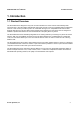
DVG-N5412SP User’s Manual Product Overview 1. Introduction 1-1 Product Overview The DVG-N5412SP is designed to carry both voice and facsimile over the IP network and wirelessly share Internet access. It uses the industry standard SIP call control protocol so as to be compatible with free registration services or VoIP service providers’ systems. As a standard user agent, it is compatible with all common Soft Switches and SIP proxy servers.
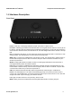
DVG-N5412SP User’s Manual Telephone Interface Description 1-2 Hardware Description Front Panel Power: Power LED. A steady light indicates a proper connection to a power source. Prov./Alm.: A blinking light indicates the DVG-N5412SP can not register with SIP Server or can not get the IP address. A blinking light also indicates the DVG-N5412SP is attempting to connect with the Provisioning server. Once the service connects, the LED will turn off.
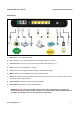
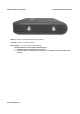
DVG-N5412SP User’s Manual Telephone Interface Description Rear Panel 1. WiFi Switch: Turn on/off wireless LAN. 2. Line: Connect to your original telephone line on the wall jack with RJ-11 cable. 3. Phone Port (1-2): Connect to your phones using standard phone cabling (RJ-11). 4. USB: Connect to a 3G USB dungle or a printer. 5. LAN: Connect to your Ethernet enabled computers using Ethernet cabling. 6. WAN: Connect to your broadband modem using an Ethernet cable. 7.
DVG-N5412SP User’s Manual Telephone Interface Description WPS: WPS button for wireless WPS-PBC setup method. Antenna: Connect to a wireless network. Reset button: Use to restore factory default settings. Use Reset Button to restore factory default settings: 1. Press and hold the reset button for 5 seconds. 2. As Alarm indicator is blinking, please release the reset button. Factory settings will be restored. D-Link Systems, Inc.
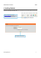
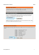
DVG-N5412SP User’s Manual SETUP 2. Getting Started To access the web-based configuration utility, open a web browser such as Internet Explorer and enter the IP address of the DVG-N5412SP from WAN port. Open your Web browser and type http://192.168.8.254 into the URL address box. Press the Enter or Return Key. Click Login to enter Web Site. D-Link Systems, Inc.
DVG-N5412SP User’s Manual SETUP Click Setup Wizard. Click Next. D-Link Systems, Inc.
DVG-N5412SP User’s Manual SETUP The username of ADMIN and USER have been defined and locked by default. It is highly recommended to create a login password to keep your VoIP Router secure. Click Next. D-Link Systems, Inc.
DVG-N5412SP User’s Manual SETUP Enter a NTP server or use the default server. Select your time zone from the drop-down menu. Enable Daylight Saving for your local time if required. Click Next. D-Link Systems, Inc.
DVG-N5412SP User’s Manual SETUP Select your Internet connection type: DHCP – Most Cable ISPs or if you are connecting the DVG-N5412SP behind a router. Static IP – Select if your ISP supplied you with your IP settings. PPPoE – Most DSL ISPs. PPTP – Select if required by your ISP. WAN1 Domain Name Server – Select Manual to manually enter IP address of DNS or select Auto if DNS is assigned by ISP. Click Next. D-Link Systems, Inc.
DVG-N5412SP User’s Manual SETUP Register to the SIP Proxy Server by clicking Enable support of SIP Proxy Server. Enter Proxy Server IP/Domain and Port. Outbound Proxy Support is optional. To register, please click on the Outbound Proxy Support box and enter Outbound Proxy IP/Domain and Port in it. Registration by phone line: Enter Number, User ID/Account and Password supplied by your ITSP. Check on the Register box to register to Proxy Server. Click Next. D-Link Systems, Inc.
DVG-N5412SP User’s Manual SETUP Click on the Enable wireless LAN interface check box to build a wireless network. Enter the SSID to name your wireless network. All devices must have the same SSID to communicate on the wireless network. Select a clear wireless channel. Select the 802.11 Mode of your network which can work in different speed of wireless connection. Click Next. Select Security Mode for your wireless network. Click Next. D-Link Systems, Inc.
DVG-N5412SP User’s Manual SETUP Setup is finished. Check the summary of your settings. To make new settings effective, you must click on the Restart button to reboot the DVG-N5412SP. Click Restart. D-Link Systems, Inc.
DVG-N5412SP User’s Manual SETUP 3. VoIP Router Web Configuration 3-1 SETUP 3-1-1 Internet Setup WAN (Wide Area Network) Settings are used to connect to your ISP (Internet Service Provider). The WAN settings are provided to you by your ISP and oftentimes referred to as "public settings". Please select the appropriate option for your specific ISP. IP Configuration (Setting WAN Port) There are five methods of obtaining a WAN port IP address: 1. DHCP, which means a Dynamic IP (Cable Modem) 2. Static IP 3.
DVG-N5412SP User’s Manual SETUP SETUP → Internet Setup SETUP → Internet Setup DHCP: Select this option if your ISP (Internet Service Provider) provides you an IP address automatically. Cable modem providers typically use dynamic assignment of IP Address. The Host Name field is optional but may be required by some Internet Service Providers. SETUP → Internet Setup Static IP: Select this option if your ISP (Internet Service Provider) provides you a Static IP address.
DVG-N5412SP User’s Manual SETUP SETUP → Internet Setup PPPoE: Select this option if your ISP requires you to use a PPPoE (Point-to-Point Protocol over Ethernet) connection. Enter the PPPoE Account, PPPoE Password and re-enter Password to confirm. SETUP → Internet Setup PPTP: Point-to-Point Tunneling Protocol (PPTP) is a WAN connection. Enter the IP Address, Subnet mask, PPTP Server, PPTP ID and Password. D-Link Systems, Inc.
DVG-N5412SP User’s Manual SETUP SETUP → Internet Setup 3G USB Adapter: 3G/3.5G WISP. Enter Username, Password, Dial Number and APN to connect to Internet via 3G/3.5G WISP. Users could also select a configured WISP from the list and DVG-N5412SP will fill necessary parameter automatically. SETUP → Internet Setup WAN Link Speed: Select WAN port link speed. SETUP → Internet Setup VoIP Connection Interface: Select a WAN interface for DVG-N5412SP VoIP traffic. D-Link Systems, Inc.
DVG-N5412SP User’s Manual SETUP SETUP → Internet Setup Factory Default MAC Address: The original MAC address of the VoIP Router. Your MAC Address: It is left blank as you log-in via the WAN port. Current MAC Address: It shows the current MAC Address if you ever used the different MAC address from Factory Default MAC Address. You can click Clone to automatically copy the MAC address of the Ethernet Card installed in the computer used to configure the device.
DVG-N5412SP User’s Manual SETUP VLAN is optional. It works with the Router or Switch that supports VLAN tag. By adding VLAN tag in packets may improve efficiency of voice traffic performance and security. Enable VLAN Tagging: It is to tag the packets for VLAN Router or Switch identifying. VLAN ID: It is to assign uniquely a user-defined ID to each packet. Priority: It is the proprietary to VLAN Router or Switch. Note: Please do not change anything here unless requested by your ISP. D-Link Systems, Inc.
DVG-N5412SP User’s Manual SETUP 3-1-2 VoIP Setup In this section, it supports registration to multiple Proxy Servers which is allowed to choose ITSP by user manually. If any registration problem occurs, please consult your VoIP Service Provider. SETUP → VoIP Setup Clink Edit icon to modify the settings. The same configurations and applications apply to three Proxy Servers. Select one of three Proxy Servers for SIP configuration. D-Link Systems, Inc.
DVG-N5412SP User’s Manual SETUP SETUP → VoIP Setup Enable Support of SIP Proxy Server / Soft Switch: Check the box to register the VoIP Router with SIP proxy server or soft switch. ITSP Name: Enter the name of ITSP. SETUP → VoIP Setup FXS Representative Number registers to Proxy: Number: Enter the representative number for Line 1 and Line 2. If the VoIP Router is configured to register with SIP proxy server, Line 1 and Line 2 are using this number to call through SIP proxy server.
DVG-N5412SP User’s Manual SETUP SETUP → VoIP Setup Each line registers to Proxy independently: Number: Enter the number, text or number and text in this field. It is the Caller ID for the called party when you make a VoIP call. If you register the VoIP Router to a SIP proxy server, then it should be the number that provided by SIP proxy server. Number and User ID/Account are usually the same from most SIP proxy severs. Each line has a number. And the number of each line is not reiteration.
DVG-N5412SP User’s Manual SETUP SETUP → VoIP Setup Proxy Server IP/Domain: Enter the IP address or URL (Uniform Resource Locator) of SIP proxy server or soft switch. Proxy Server Port: Enter the SIP proxy server’s listening port for the SIP in this field. Leave this field to the default if your VoIP Service Provider did not give you a server port number for SIP. Proxy Server Realm: Enter the realm for SIP proxy server. It is used for authentication in a SIP server.
DVG-N5412SP User’s Manual SETUP SETUP → VoIP Setup Outbound Proxy Support: Check the box to send all SIP packets to the destined outbound proxy server. An outbound proxy server handles SIP call signaling as a standard SIP proxy server would do. Further, it receives and transmits phone conversation traffic (media) between two communication parties. This option tells the VoIP Router to send and receive all SIP packets to the destined outbound proxy server rather than the remote VoIP device.
DVG-N5412SP User’s Manual SETUP For example (Example in Taiwan), If Server 1 is local VoIP Service Provider you can refer to Digit Map page for general settings. If Server 2 is global VoIP Service Provider (VoIP STUN, free to dial to some cities free charge) you can set individual dialing plan for VoIP STUN in Number Translation field. Scan Code can be your dialing custom, and VoIP Dial-out is the number on the basis of the dialing rule needed by VoIP STUN.
DVG-N5412SP User’s Manual SETUP 3-1-3 Wireless Setup This section instructs you how to setup your wireless network on the VoIP Router device. Setup Hint: 1. 2. 3. Every device in the same wireless network must use the same SSID. To avoid wireless network overlap, a specific and different channel is needed. Make sure security used by every device in the same wireless network is compatible with the wireless AP.
DVG-N5412SP User’s Manual SETUP 802.11n only - Allow all 802.11n compliant wireless devices to associate with the wireless AP. Mixed 802.11g and 802.11b - Allow a mix of both IEEE802.11g and 802.11b compliant wireless devices to associate with the wireless AP. Mixed 802.11n and 802.11g - Allow a mix of both IEEE802.11n and 802.11g compliant wireless devices to associate with the wireless AP. Mixed 802.11n, 802.11g and 802.11b - Allow a mix of both IEEE802.11n, 802.11g and 802.
DVG-N5412SP User’s Manual SETUP 3-1-3-2 Wireless Security This section introduces you different ways of wireless security you can setup. It is important to enable secure algorithm to protect your data from eavesdropping by unauthorized wireless users. SETUP -> Wireless Setup -> Wireless Security Select DDID: Select an SSID to configure wireless security mechanism. Security Mode: Select the encryption/authentication type: None, WPA, WPA2 and WPA2 Mixed. D-Link Systems, Inc.
DVG-N5412SP User’s Manual SETUP WPA Authentication Mode The wireless network can use WPA Authentication to verify whether a wireless device is allowed to access your Access Point or not. You can choose to use Enterprise (RADIUS) method or Personal (Pre-Shared Key). The encryption mechanism used for RADIUS and WPA-PSK is the same. The difference between the two is that WPA-PSK uses a specific characters sting like password instead of a user-authentication.
DVG-N5412SP User’s Manual SETUP SETUP -> Wireless Settings -> Wireless Security (WPA) Select the type of WPA (WPA, WPA2, WPA2 Mixed), choose the proper security mode according to your wireless network. WPA Authentication Mode: Select Enterprise (RADIUS). WPA Cipher Suite: WPA Cipher Suite is used for the configuration of WPA or WPA2 Mixed. TKIP - TKIP is the security protocol used in WPA. The length of TKIP encryption is longer than WEP encryption that increases the complexity of decoding for crackers.
DVG-N5412SP User’s Manual SETUP SETUP -> Wireless Setup -> Site Survey Site Survey When wireless client mode is enabled, click the Refresh button to display any Access Point on your wireless network so that a wireless client can obtain SSID, BSSID, Channel, Type, Encryption, and Signal through scanning using this Site Survey tools. Example: 1. Select the Wireless AP and click Accept bottom. 2. Enter the password of the Wireless AP and click Apply bottom. 3.
DVG-N5412SP User’s Manual SETUP 3-1-3-3 WPS SETUP -> Wireless Setup -> WPS It allows users establish wireless connect between DVG-N5412SP and computers via WPS(Wireless Protect Setup) method. Example for setting Wiresess profile via WPS method on Windows 7. Enter [Network and Sharing Center] Click [Set up a new connection or network] D-Link Systems, Inc.
DVG-N5412SP User’s Manual SETUP Click [Connect to the Internet] Click [Wireless] D-Link Systems, Inc.
DVG-N5412SP User’s Manual SETUP Select a Wireless AP. Click [OK] to start setup. D-Link Systems, Inc.
DVG-N5412SP User’s Manual SETUP Enter the 8-digit PIN from DVG-N5412SP label then click Next. Note: If you have ever click “Change PIN” button on the WEB UI of DVG-N5412SP, please enter the PIN number displaied on WEB GUI. Type network name(SSID) then click Next. D-Link Systems, Inc.
DVG-N5412SP User’s Manual SETUP Wait for Windows 7 setting up wireless network. Configuration finished, you could connect to DVG-N5412SP at present. You could also print security key of save this profile for another computer to add this wireless network manually. Note: DVG-N5412SP supports WPS work with WindowsR Vista and Windows 7 only. D-Link Systems, Inc.
DVG-N5412SP User’s Manual SETUP 3-1-4 LAN Setup SETUP → LAN Setup LAN Port Address: Enter the LAN IP address of the VoIP Router. It is also the default gateway for DHCP clients. Subnet Make: Enter the subnet mask for DHCP clients. D-Link Systems, Inc.
DVG-N5412SP User’s Manual SETUP SETUP → LAN Setup Enable DHCP Server: This variable is to assign the IP address for the devices connected to LAN port of the VoIP Router. IP Pool Starting Address: Enter the starting IP address for the DHCP server's IP assignment. IP Pool Ending Address: Enter the ending IP address for the DHCP server's IP assignment. IP Pool Uses Other Default Gw: Check the box to assign different default gateway for DHCP clients.
DVG-N5412SP User’s Manual SETUP SETUP → LAN Setup Enable Port: It is to active/des-active LAN port physical connection. Incoming Rate Limit: Set the incoming (from LAN to WAN) rate limit of a specific LAN port (can not exceed the real downstream bandwidth). Outgoing Rate Limit: Set the outgoing (from WAN to LAN) rate limit of a specific LAN port (can not exceed the real upstream bandwidth).
DVG-N5412SP User’s Manual SETUP 3-1-5 USB Settings SETUP → USB Settings USB Type: Select a USB device type. 3G USB Adapter: It allows you plug in a 3G dungle dial to WISP for Internet access. Share Port: Connect USB device such as a printer, scanner or MFP(Multifunction Printer) to DVG and share it at Local Area Network. Please refer to Share Port User Manual for USB Share Port application.
DVG-N5412SP User’s Manual SETUP 3-1-6 Time and Date SETUP → Time and Date Automatically synchronize with Internet time servers: The VoIP Router should automatically sync up with time servers. First NTP time server: Select the desired domain name of a NTP server as first priority. Second NTP time server: Select the domain name of a NTP server as second priority. Current Router Time: It shows the current time of the VoIP Router. Time Zone: Select your time zone from the drop-down menu.
DVG-N5412SP User’s Manual ADVANCED 3-2 ADVANCED 3-2-1 VoIP 3-2-1-1 Caller Filter This function allows you to accept or reject any incoming call from the IP address listed in the filter rule. The call from the IP address of SIP proxy server is always accepted, despite Deny is selected or the IP address of SIP proxy server is not in the filter rule of Allow. ADVANCED → VoIP → Caller Filter Caller Filter: It is to allow or deny the filter rule. Status: It is to show the status of enable or disable.
DVG-N5412SP User’s Manual ADVANCED 3-2-1-2 Caller ID ADVANCED → VoIP → Caller ID FXS Caller ID Generation: Select DTMF, FSK or FSK+Type II Caller ID to enable the caller ID display function on FXS port. When enabled, the caller’s phone number will be displayed on your phone set when the call comes through. FSK+Type II Caller ID is used for displaying the caller ID when receiving call waiting calls. Note: Make sure that your phone set supports Type II Caller ID before you select it.
DVG-N5412SP User’s Manual ADVANCED 3-2-1-3 Calling Features ADVANCED → VoIP → Calling Features Do Not Disturb: Check the box to reject (busy tone played) incoming calls. Unconditional Forward: Check the box to forward incoming calls to the assigned “Forwarding Number” automatically. Busy Forward: Check the box to forward incoming calls to the “Forward incoming Number” when the line is busy.
DVG-N5412SP User’s Manual ADVANCED ADVANCED → VoIP → Calling Features Enable Call Feature Code: Check the box to enable/disable some call feature codes through a phone set. Call pickup: Allow one to pick up someone else’s telephone call. Call Back on Busy: Your phone will ring back the last number that called you. Blink Transfer: Blind Transfer involves passing a call without notifying the recipient. Call Feature Code Instructions (example): 1.
DVG-N5412SP User’s Manual ADVANCED Calling Feature Instructions: Call Hold: The call will be held after the FLASH button is pressed on the phone set. The VoIP Router will play a hold music (provided by your ITSP or VSP) to the remote end. Call Transfer: The call will be held after FLASH button is pressed on local phone set (the VoIP Router plays on-hold music to the remote end). Meanwhile, the local user can dial out another number after the dial tone is heard.
DVG-N5412SP User’s Manual ADVANCED 3-2-1-4 Codec ADVANCED → VoIP → Codec Jitter Buffer: Enter the jitter of receiving packets. Silence Detection / Suppression: Check the box to enable the silence packets and send less voice data (package) during the silent period while talking. Echo Canceling: Check the box to remove echo and improve voice quality during conversation. RTCP-XR: Enable RTCP-XR(RFC-3611) to report network quality. Codec: Check the box to codec for the VoIP Gateway to support.
DVG-N5412SP User’s Manual ADVANCED 3-2-1-5 CPT/Cadence ADVANCED → VoIP → CPT / Cadence CPT # 1 Enable Setting 1: Define the call process tones for the DVG-N5412SP generates. ADVANCED → VoIP → CPT / Cadence FXS Ring Cadence Settings: Specify the ring cadence for the FXS port. In this field, you specify the on and off pulses for the ring. The ring cadence that should be configured differs depending on local PSTN or PBX settings and requirements. D-Link Systems, Inc.
DVG-N5412SP User’s Manual ADVANCED 3-2-1-6 Digit Map Digit Map supports multiple dial plans which help users to arrange least cost route. Each Proxy Server has individual dial plan which combines the original feature of Digit Map and Speed Dial. You can use “?” or “%” in the column of Scan Code and VoIP Dial-out. “?” represents a single digit, and “%” represents a wildcard.
DVG-N5412SP User’s Manual ADVANCED ADVANCED → VoIP → Digit Map → VoIP Route Profile There are 10 VoIP route profiles. Each VoIP route profile provides four routes to select. Server 1, Server 2, Server 3, Phone Book and None can be selected for each route. Example of VoIP Route Profile: Assume that VoIP TA is registered to three servers. Server 1 is local VoIP Service Provider. Server 2 is VoIP STUN (free to dial to some cities without charge). Server 3 is VSP in UK. D-Link Systems, Inc.
DVG-N5412SP User’s Manual ADVANCED Example 1 – Single VoIP route, The number translation of each server is blank. The VoIP route profile appears like: Digit Map Table appears like: As you dial the phone numbers starting with 09, like 0912345678, the call will only go through Server 1 (local VSP). If Sever1 is failed, the call will be diverted to PSTN. D-Link Systems, Inc.
DVG-N5412SP User’s Manual ADVANCED Example 2 – Multiple Route, The number translation of Server 1 is blank, and the number translation of Server 2 appears like: The VoIP route profile appears like: Digit Map Table appears like: As you dial the phone numbers staring with 03, like 0312345678, the number will be changed to 0045312345678, followed the number translation of Server 2, and the call will go through Server 2 (free VSP) at first.
DVG-N5412SP User’s Manual ADVANCED Example 3 – Multiple Route, The number translation of Server 1 is blank, and the number translation of Server 2 appears like: The number translation of Server 3 appears like: The VoIP Route Profile appears like: D-Link Systems, Inc.
DVG-N5412SP User’s Manual ADVANCED Digit Map Table appears like: As you dial the phone numbers staring with 00244, like 00244123456789, the number will be changed to 0123456789 followed the number translation of Server3, and the call will go through Server 3 (UK VSP) at the first. If the first route is failed, the number is changed to 0044123456789, and the route is changed to Server 2 (free VSP).
DVG-N5412SP User’s Manual ADVANCED For example, Scan Code: 091 VoIP Dial-out: 0912345678 PSTN Dial-out: leave it as blank User Dial Length: 2 Route: Auto VoIP Route Profile: Route # 1 Pick up the handset and dial 091, and the system will do the things as follow: 1. Change the phone number to the global number. 091 is changed to 0912345678. Then, follow the VoIP Route Profile # 1. 2. If Server 1 is failed, because of Route is Auto, the call is diverted to PSTN.
DVG-N5412SP User’s Manual ADVANCED For example, Scan Code: 4% VoIP Dial-out: 00244% PSTN Dial-out: leave it as blank User Dial Length: 11 Route: Auto VoIP Route Profile: Route # 3 Pick up the handset and dial 4323456789. The system will do the things as follow: 1. Change the phone number to the global number. 4323456789 is changed to 00244323456789. Then, follow the VoIP Route Profile # 3. 2. Translate the global number to the private number followed the number translation of Server 3.
DVG-N5412SP User’s Manual ADVANCED Method 3- Substitution: It helps you dial to destination that you can not dial by phone. Destination like: anny@sip.com.uk. Fill the number into the Scan Code column and enter the desired name into the VoIP Dial-out column. For example, Scan Code: 11 VoIP Dial-out: AnnyKC PSTN Dial-out: leave it as blank User Dial Length: Disable Route: VoIP VoIP Route Profile: Route # 5 Pick up the handset and dial 11. The system will do the things as follow: 1.
DVG-N5412SP User’s Manual ADVANCED 3-2-1-7 DTMF & PULSE ADVANCED → VoIP → DTMF & PULSE Dial Wait Timeout: Enter the timeout duration after the user picks up the phone set. Inter Digits Timeout: Enter the timeout duration between the intervals of each key pressed. When exceeding the set timeout duration without entering further digits, the numbers entered will be dialed out.
DVG-N5412SP User’s Manual ADVANCED 3-2-1-8 Fax ADVANCED → VoIP → FAX Option Fax Detection Content of SDP of re-INVITE re-INVITE with T.38 from remote party Disable No N/A Accept and change RTP to T.38 T.38 Fax Yes re-INVITE with T.38 and T.30 Accept and change RTP to T.38 T.30 Fax Yes re-INVITE with T.30 Accept and change RTP to T.38 T.30 Fax/Modem Detect CED only re-INVITE with T.30 Accept and change RTP to T.38 T.30 Only No N/A Accept and change RTP to T.38 T.
DVG-N5412SP User’s Manual ADVANCED ADVANCED → VoIP → FAX Switch FAX On CED Detection: DVG will send FAX Re-Invite immediately as it detect FAX CED tone, that will save handshaking time between FAX machines. Restrict T.38: DVG will reject T.38 Re-invite in case the FAX type contains without T.38. FAX Detection Sensitivity: To set higher value to make DVG to be more sensitive. High Speed Redundancy: Set redundancy packets for FAX image. It could repair FAX image for non-continuous packets lost.
DVG-N5412SP User’s Manual ADVANCED 3-2-1-9 Hot Line ADVANCED → VoIP → Hot Line Hot Line: Check to direct the call automatically to a pre-configured destination without any action when the FXS is off-hook. (ie. as the user picks up the phone). When the FXS is under Hot Line mode, no other phone numbers can be dialed. Hot Line No.: Enter the number for pre-defined destination. Warm Line: Enter the time for the call to start with a pause, so the user can dial another number.
DVG-N5412SP User’s Manual ADVANCED 3-2-1-10 Line ADVANCED → VoIP → Line Enable: Tick the check box to enable a line. If some lines are not used, disable them (Pause Function) to avoid unnecessary waiting when an incoming call is diverting to the line. Listening Volume: Use the drop-down menu to adjust the hearing (listening) volume. Speaking Volume: Use the drop-down menu to adjust the speaking volume. Tone Volume: Use the drop-down menu to adjust the tone volume.
DVG-N5412SP User’s Manual ADVANCED ADVANCED → VoIP → Line Enable: Tick the check box to enable a line. If some lines are not used, disable them (Pause Function) to avoid unnecessary waiting when an incoming call is diverting to the line. Flash Time: Enter the time for PSTN to detect if the voltage keeps the on-hook status. PSTN Ring OFF Length: Enter the ring length detected if the remote party is on-hook from PSTN by PSTN port.
DVG-N5412SP User’s Manual ADVANCED Ring (Early Media) Time Limit[10 - 600secs]: Enter the timeout to cancel a call if no one answers the phone. Enable End of Digit Tone: Check the box to activate the function of playing a “Beep-Beep” tone to notify the user that the call is in progress. Force Calling Thru PSTN Code: Fill prefix code to dial out through PSTN(Life Line) port.
DVG-N5412SP User’s Manual ADVANCED ADVANCED → VoIP → Line This feature is a call drop standard for a VoIP Router to determine whether or not to hang up the phone. The VoIP Router will disconnect the call automatically to avoid keeping the line engaged if the detected volume is below the Silence Detection Threshold or the time exceeds the Drop Silent Call Timeout. Silence Detection Threshold: Enter the threshold (dB) to detect if there is voice coming from RJ-11 interface.
DVG-N5412SP User’s Manual ADVANCED 3-2-1-11 Phone Book Phone Book: It is used for peer-to-peer communication. Some peer information needs to be added to this section prior to making peer-to-peer calls. You need to enter the phone number and the IP address of the remote peer. ADVANCED → VoIP → Phone Book Gateway Name: Enter the alias of the remote peer. Gateway Number: Enter the phone number of the remote peer. IP / Domain Name: Enter the IP address or URL (Uniform Resource Locator) of the remote peer.
DVG-N5412SP User’s Manual ADVANCED 3-2-1-12 SIP Advanced ADVANCED → VoIP → SIP Advanced Listen Port UDP: Enter the VoIP Router’s listening port in this field. Leave it as default settings, unless it conflicts with ports used by other device in your network. RTP Starting Port UDP: Enter the starting port number or transmitting voice data among VoIP devices. Each line requires 2 ports.
DVG-N5412SP User’s Manual ADVANCED Note: E.164 Numbering depends on the proxy. If you fail to make a call, please contact your VoIP Service Providers. ADVANCED → VoIP → SIP Advanced Session Expiration: This field will set the time that the VoIP Router will allow a SIP session to remain die (without traffic) before dropping it. Session Refresh Request: Select UPDATE or re-INVITE to send refresh requests to the Server.
DVG-N5412SP User’s Manual ADVANCED ADVANCED → VoIP → SIP Advanced Anonymous Caller ID (CLIR): Check the box to lock the delivery of the Caller ID to the called party. VoIP Call Out Notification: Check the box to enable the function of playing a tone to notify user that the call is through VoIP. Enable Built-in Call Hold Music: Check the box to enable the function of playing music when receiving Call Hold request.
DVG-N5412SP User’s Manual ADVANCED SIP Caller ID Obtaining: Select the part of the SIP packet from the VoIP Gateway to obtain Caller ID. There are several places where the Caller ID is located. Remote-Party-ID Display Name - It is located at SIP → Remote-Party-ID → Before [
DVG-N5412SP User’s Manual ADVANCED 3-2-2 Access Control 3-2-2-1 MAC Filtering Use MAC Filters to deny computers within the local area network from accessing the Internet. You can either manually add a MAC address that are connected to the VoIP Router. ADVANCED → Access Control → MAC Filtering Enable MAC Filtering: Check the box to deny from accessing Internet. MAC: Enter the MAC of the computer in the LAN (Local Area Network) to be used in the MAC filter table. Remark: Enter comments.
DVG-N5412SP User’s Manual ADVANCED 3-2-3 Firewall and DMZ 3-2-3-1 DMZ DMZ (Demilitarized Zone) allows the server on the LAN site to be directly exposed to the Internet for accessing data and to forward all incoming ports to the DMZ Host. Adding a client to the DMZ may expose that computer to a variety of security risks; so only use this option as a last resort. ADVANCED → Firewall and DMZ → DMZ Enable DMZ: Check the box to enable DMZ feature.
DVG-N5412SP User’s Manual ADVANCED 3-2-3-2 DoS Prevention ADVANCED → Firewall and DMZ → DoS Prevention Enable DoS Prevention: Check the box to prevent DoS attacks from WAN or LAN. There are various types of DoS attacking. Leave settings in this field to the default if you are not familiar with it. D-Link Systems, Inc.
DVG-N5412SP User’s Manual ADVANCED 3-2-3-3 IP Filtering Use IP Filters to deny particular LAN IP addresses from accessing the Internet. You can deny specific port numbers or all ports for a specific IP address. The screen will display well-known ports that are defined. To use them, click on the edit icon. You will only need to input the LAN IP address(es) of the computer(s) that will be denied Internet access.
DVG-N5412SP User’s Manual ADVANCED 3-2-3-4 Port Filtering Port filtering enables you to control all data that can be transmitted over routers. When the port used at the source end is within the defined scope, it will be filtered without transmission. ADVANCED → Firewall and DMZ→ Port Filtering Enable Port Filtering: This variable is to restrict certain types of data packets by port. Port Range: Enter the port range that will be denied access to the Internet.
DVG-N5412SP User’s Manual ADVANCED 3-2-3-5 Virtual Server Enable users on Internet to access the WWW, FTP and other services from your NAT. It is also known as port forwarding. When remote users are accessing Web or FTP servers through WAN IP address, it will be routed to the server with LAN IP address. ADVANCED → Firewall and DMZ→ Virtual Server Enable Virtual Server: Check the box to enable port forwarding. WAN Port Range: Enter the port range for the WAN side.
DVG-N5412SP User’s Manual ADVANCED 3-2-4 Advanced Wireless 3-2-4-1 Advanced This section introduces advanced configuration for the wireless access point. If you are not familiar with the following functions, keep the default parameters. In some cases, incorrect settings may reduce wireless performance. ADVANCED -> Advanced Wireless -> Advanced Fragmentation: A packet can be fragmented into small units to pass over a network medium that can not support the original packet size.
DVG-N5412SP User’s Manual ADVANCED 3-2-4-2 Access Control The Access Control setting provides a service that you can control different access rights for different wireless clients connected to your VoIP Router. The local and remote stations are limited to access Internet through your Access Points using MAC address of wireless client. Choose the appropriate Access Control Services from Wireless Access Control Mode option.
DVG-N5412SP User’s Manual ADVANCED 3-2-5 Advanced Network 3-2-5-1 QOS WAN QoS ADVANCED → Advanced Network → QoS Enable WAN QoS: Check the box to guaranty the voice quality. The system reserves the bandwidth for voice packets, and the data transmission is distributed to less bandwidth. Downstream Bandwidth - Select the downstream bandwidth that is less than the actual bandwidth subscribed from the drop-down menu.
DVG-N5412SP User’s Manual ADVANCED 3-2-5-2 NAT Traversal If your VoIP Router is set up behind an Internet sharing device, you can select either the NAT or STUN protocol. ADVANCED → Advanced Network → NAT Traversal Enable NAT Public IP: Check the box to use the IP address of the Internet sharing device if the VoIP Router is set up behind an Internet sharing device. Also the VoIP Router will use the IP address of the Internet sharing device as the public IP when it connects to Internet.
DVG-N5412SP User’s Manual ADVANCED 3-2-5-3 STUN Inquiry Use “STUN Inquiry” to detect your IP sharing device’s NAT type and communication between a STUN server and client. ADVANCED → Advanced Network → STUN Inquiry NAT Type: It shows the NAT type of your router. STUN Server IP/Domain: Enter the IP address or URL of the STUN server for query. STUN Server Port: Enter the STUN Server’s listening port D-Link Systems, Inc.
DVG-N5412SP User’s Manual ADVANCED 3-2-5-4 Static Route Build static routes within an internal network. These routes will not apply to the Internet. ADVANCED → Advanced Network → Static Route Route: Destination network of the route. Route Mask: Subnet mask to apply on destination network. Next Hop IP: The next hop IP address to the specified network. Interface: The interface attached to this route. 3-2-5-5 UPnP ADVANCED → Advanced Network → UPnP Enable UPnP: Check the box to enable UPnP device on DVG.
DVG-N5412SP User’s Manual ADVANCED 3-2-5-6 RIP ADVANCED → Advanced Network → RIP Enable RIP: Check the box to enable RIP to build small-multi router network via RIP protocol. This function is useless for home network. D-Link Systems, Inc.
DVG-N5412SP User’s Manual ADVANCED 3-2-6 SNMP ADVANCED → Advanced Network → SNMP DVG-N5412SP supports SNMP V1, V2 and V3. Please enter required parameter for SNMP V3 on each SNMP setting pages.
DVG-N5412SP User’s Manual ADVANCED Set [Advanced-> SNMP Management-> SNMP View-> View Name] as “all”. Set [Advanced-> SNMP Management-> SNMP View-> View Name] as “.1” Set [Advanced-> SNMP Management-> SNMP Community-> Community Name] for public and private. Select a configured View Name. D-Link Systems, Inc.
DVG-N5412SP User’s Manual MAINTENANCE 3-3 MAINTENANCE 3-3-1 Device Management MAINTENANCE → Device Management Note: There are two operating levels when entering the Web UI. Logging-in as the ADMIN allows you to change all settings. A Web UI USER only has access to some settings. Password: By default there is no password configured. It is highly recommended that you create a password to keep your router secure.
DVG-N5412SP User’s Manual MAINTENANCE 3-3-2 Backup and Restore Save and Reboot MAINTENANCE → Backup and Restore Save All Settings: Click the Save All Settings check box and reboot the system after completing changes. The new settings will take effect after the VoIP Router is restarted. Restart: Click the Reboot button to reboot the system. Backup Configurations File MAINTENANCE → Backup and Restore The current system settings can be saved as a file onto the local hard drive.
DVG-N5412SP User’s Manual MAINTENANCE Backup Configurations Template File MAINTENANCE → Backup and Restore Click the Backup Settings button to save your current settings to a template file for editing. Update Settings MAINTENANCE → Backup and Restore To restore a system settings file, click on Browse to search the local hard drive for the file to be used. Once you locate the file, click Upload Settings to overwrite the current settings with the settings saved to the file.
DVG-N5412SP User’s Manual MAINTENANCE 3-3-3 Firmware Update The VoIP Router supports a software upgrade function from a remote server. Please consult your VoIP Service Provider for information about the following details. MAINTENANCE → Firmware Update Upgrade Server: Select the upgrade type: TFTP, FTP, or HTTP. Server IP Address: Enter the server’s IP address. Server Port: Enter the server’s port. User Name/ Password: Enter the account information for accessing the server if needed.
DVG-N5412SP User’s Manual MAINTENANCE 3-3-4 Dynamic DNS ADVANCED → Dynamic DNS Enable Dynamic DNS: Check the box to enable DDNS function. It is only necessary when the VoIP Router is set up behind an Internet sharing device that uses a dynamic IP address and does not support DDNS. Server address: Select a DDNS service from the drop and down arrow. Hostname: Enter the URL of the system (or NAT) – applied from domain name registration providers (e.g. www.dyndns.org).
DVG-N5412SP User’s Manual MAINTENANCE 3-3-5 Log Settings MAINTENANCE → Log Settings Enable: Check the box to send event notification messages across IP networks to the Server. Server Address: Enter the System Log Server’s IP address. Port: Enter the System Log Server’s listening port. Leave this field to the default if your VoIP Service Provider did not provide you a server port number for System Log Server. D-Link Systems, Inc.
DVG-N5412SP User’s Manual MAINTENANCE 3-3-6 Diagnostics 3-3-6-1 Ping Test Use “Ping” to verify if a remote peer is reachable. Enter a remote IP address and click “Test” to ping the remote host. The result would be shown on Result Table MAINTENANCE → Diagnostics → Ping Test D-Link Systems, Inc.
DVG-N5412SP User’s Manual MAINTENANCE 3-3-6-2 Outward Test MAINTENANCE → Diagnostics → Outward Test It allows operator to verify whether it is some problem on the cable between phone sets and DVG-N5412SP FXS ports. Enable: Select the lines you want to test. Including Channel In Used: Since the line test will interrupt a talking call, that DVG-N5412SP will ignore the in used line. If you would like to test all the lines you select even it is in used, please tick this item. Test: Click start to test.
DVG-N5412SP User’s Manual MAINTENANCE 3-3-6-3 FXS Inward Self Test MAINTENANCE → Diagnostics → Inward Test It allows operator to verify if it is some problem on the FXS chip set. Enable: Select the lines you want to test. Including Channel In Used: Since the line test will interrupt a talking call, that DVG-N5412SP will ignore the in used line. If you would like to test all the lines you select even it is in used, please tick this item. Test: Click start to test.
DVG-N5412SP User’s Manual MAINTENANCE 3-3-7 TR069 TR069 allows operator to manage DVG-N5412SP with a TR069 standard protocol. Note: Fill in the parameters needed by your VoIP Service Provider. Please check with your VoIP Service Provider about the availability of these services. Advanced Settings → TR069 Enable TR069: Check the box to start TR069 service Username: Enter an available ACS user name. Password: Enter the ACS password. Auto Config.
DVG-N5412SP User’s Manual MAINTENANCE Connection Request Username: Enter username for remote trigger. Connection Request Password: Enter password for remote trigger. Note: Contact your server provider if necessary. MAINTENANCE → TR069 Binding Server for Trigger: Check the box to trigger a connection between Provisioning Server and the VoIP Gateway. Provisioning Server will bind a port for the VoIP Gateway to send provision request.
DVG-N5412SP User’s Manual MAINTENANCE 3-3-8 CDR The user can set up a CDR Server to record call details for every phone call with TCP protocol. The present CDR provides the call event such as HOOK ON, HOOK OFF, DIALED NUMBER, DATE…recording in a text file and which can be imported to prepare an analysis report. MAINTENANCE → CDR Send record to CDR Server: Tick the check box to enable the call detail recording. CDR Server IP / Domain: Enter the IP address of the CDR server.
DVG-N5412SP User’s Manual STATUS 3-4 STATUS 3-4-1 Device Info STATUS → Device Info For WAN Port Information, it shows IP address, subnet mask, default gateway and DNS server. If you use PPPoE to obtain IP, you will know if the IP is obtained through this method. If IP address, subnet mask, default gateway is blank, it means that the VoIP Router does not obtain IP. For LAN Port Information, it shows LAN port IP, subnet mask, and the status of DHCP server.
DVG-N5412SP User’s Manual STATUS 3-4-2 VoIP Status STATUS → VoIP Status For Port Status, it includes if each port registers to Proxy successfully, the last dialed number, how many calls each port has made since the VoIP Router is start, etc. Example: “S1 701” shows that the number of the first line which register to SIP Server 1 is 701. “S2 2702” shows that the number of the second line which register to SIP Server 2 is 2701.
DVG-N5412SP User’s Manual STATUS 3-4-3 LAN Client The Active Wireless Clients table displayed the identification and transmission status of active wireless clients on wireless LAN interface. The DHCP Clients table displayed LAN device that has already been assigned an address from DVG-N5412SP. You can check if the DHCP client has obtain an IP address. STATUS → LAN Client D-Link Systems, Inc.
DVG-N5412SP User’s Manual STATUS 3-4-4 Statistics STATUS → Statistics Display the information of the last call made. Press Refresh button to get the latest RTP Packet Summary. 3-4-5 Routing Table STATUS → Routing Table The Routing Table stores the information for particular network destination around the VoIP Router. Press Refresh button to generate the details. D-Link Systems, Inc.
DVG-N5412SP User’s Manual STATUS 3-4-6 Logout If setting or parameter has been changed, remember to save the changes before you logout the configuration menu. Logout D-Link Systems, Inc.
DVG-N5412SP User’s Manual VoIP Router Configuration-IVR 4. Configuring the VoIP Router through IVR VoIP transmits voice data (packets) via the Internet, hence the condition and status of the network environment is relatively important to the telecommunications quality. If any one of the parties involved in VoIP communications has insufficient bandwidth or frequent packet loss, the telecommunication quality will be poor.
DVG-N5412SP User’s Manual VoIP Router Configuration-IVR Once the setting or query has been completed, you can hear a dial tone. Use the same procedure to make a second query or setting. To exit IVR mode, simply hang up the phone. Example: enter “**#” (you are now in IVR mode) enter 101 (to query the current IP address) the system responds with an IP address. You can continue with more settings or queries: enter 111 (to set a new IP address) enter 192*168*1*2 (new IP address).
DVG-N5412SP User’s Manual VoIP Router Configuration-IVR 4-1-1 IVR Functions Table: Function Description Code Example / Notes 111/101 WAN Port IP address Set/Query 112/102 WAN Port Subnet Mask Set/Query 113/103 WAN Port Default Gateway Set/Query Dial function code 114 and then dial 1 for a Static IP connection then setup the IP address.
DVG-N5412SP User’s Manual VoIP Router Configuration-IVR 4-2 IP Configuration Settings—Set the IP Configuration of the WAN Port Static IP Settings Note: Complete static IP settings should include a static IP (option 1 under 114), IP address (111), Subnet Mask (112), and Default Gateway (113). Please contact your Internet Service Provider (ISP) if you have any question. Function Command Select a Static IP After entering IVR mode, dial 114.
DVG-N5412SP User’s Manual VoIP Router Configuration-IVR Select a PPPoE After entering IVR mode, dial 114. When voice prompt plays “Enter value,” dial 3 (to select PPPoE). PPPoE Account Settings After entering IVR mode, dial 121. When voice prompt plays “Enter value”, enter the account number followed by”#”. Example: If the account is “87654321@hinet.net,” please enter 08 07 06 05 04 03 02 01 71 48 49 54 45 60 72 54 45 60 #.
DVG-N5412SP User’s Manual VoIP Router Configuration-IVR 4-2-1 PPPoE Character Conversion Table: The table below provides a list of PPPoE conversion codes. The first row (high-lighted) of each pair of the column lists the numbers, alphabets or symbols and the second row (high-lighted) of each pair of the column (“Input Key”) represents the codes to be entered for the corresponding numbers, alphabets or symbols.
DVG-N5412SP User’s Manual Appendix 5. Dialing Principles 5-1 Dialing Options Dial the phone number which you want to call and press # to call out immediately. Note that if the “# (pound)” not dialed, the number will be called out after 4 seconds by default. The period between number dialed and call out is named “Inter Digits Timeout”. (Configurable from “DTMF and PULSE”, default=4 seconds, see page 50).
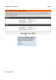
DVG-N5412SP User’s Manual Appendix 5-3 Routing To achieve maximum flexibility, the number dialed will be looked up in several tables defined by VoIP Router. If no match is found from Digit Map Table, it will then look up the number from another table and to the registered VoIP Service Provdier. Routing Processing Flow The routing after checking Digit Map Table may be vary. The routing accords with VoIP Route Profile. By default, Phone Book is the first route of VoIP Route Profile.
DVG-N5412SP User’s Manual Appendix Start Enter a phone number (D#) Change the number to Global Number. Yes Is (D#) defined in Digit Map table? No Is (D#) or Global Number defined in Phone Book table? Yes No Is (D#) or Global Number defined in Server 1? Yes No Is (D#) or Global Number defined in Server 2? Yes No Is (D#) or Global Number defined in Server 3? Yes No Dial out as defined in the first match case by VoIP Router End D-Link Systems, Inc.
DVG-N5412SP User’s Manual Appendix 6. Troubleshooting This chapter provides solutions to problems that can occur during the installation and operation of the DVG-N5412SP. Read the following descriptions if you are having problems. (The examples below are illustrated in Windows® XP. If you have a different operating system, the screenshots on your computer will look similar to the following examples.) 1.
DVG-N5412SP User’s Manual Appendix To reset the router, locate the reset button (hole) on the rear panel of the unit. With the router powered on, use a paperclip to hold the button down for 10 seconds. Release the button and the router will go through its reboot process. Wait about 30 seconds to access the router. The default IP address is 192.168.8.254. When logging in, the username is admin and leave the password box empty. 3.
DVG-N5412SP User’s Manual Appendix Appendix Product Features WAN One 10/100/1000Mbps auto-negotiation, auto-crossover RJ-45 Ethernet port Support static IP, PPPoE, and DHCP address assignment and dynamic DNS (DDNS) QoS: IP TOS (Type of Services) and DiffServ (Differentiated Services) for both SIP signaling and RTP NAT Traversal : Port Forwarding, STUN and Outbound Proxy NTP: (Network Time Protocol RFC 1305) Time Zone Support MAC Address Clone RTP Packet Summary : packet sent, packet receiv
DVG-N5412SP User’s Manual Appendix Configuration & Maintenance Configuration methods: o Web o IVR o Telnet Status reports: o Port status o Registration status o Ping tests o Hardware / software information Firmware Upgrade through TFTP, FTP or HTTP server Configuration Backup/Restore Reset button (with restore factory default function) D-Link Systems, Inc.