DSS-8+ 8-port 10/100Mbps Switch User’s Guide Rev. 03 (MAR.
TABLE OF C ONTENTS ABOUT THIS GUIDE ....................................................1 PURPOSE .........................................................................................1 OVERVIEW OF THIS USER’S GUIDE ..........................................1 INTRODUCTION ..............................................................2 FAST ETHERNET TECHNOLOGY ................................................2 SWITCHING TECHNOLOGY .........................................................2 FEATURES ....
DSS-8+ TO SWITCH (OTHER DEVICES) ..................................11 A. Using straight cable .............................................................12 B. Using crossover cable .........................................................12 PORT SPEED & DUPLEX MODE ...............................................12 INSTRUCTIONS FOR USE OF STACKING BRACKETS ............................................................................13 RJ-45 PIN SPECIFICATION ................................
A BOUT T HIS G UIDE Congratulations on your purchase of the DSS-8+. This device integrates 100Mbps Fast Ethernet and 10Mbps Ethernet network capabilities in a highly flexible desktop package. Purpose The purpose of this manual is to show you how to install and configure your DSS-8+. Overview of this User’s Guide ♦ Chapter 1, Introduction. Describes the DSS-8+ and its features. ♦ Chapter 2, Unpacking and Setup. Helps you get started with the basic installation of the DSS-8+.
I NTRODUCTION This chapter describes the features of the DSS-8+ and some background information about Ethernet/Fast Ethernet switching technology. Fast Ethernet Technology The growing importance of LANs and the increasing complexity of desktop computing applications are fueling the need for high performance networks. A number of high-speed LAN technologies have been proposed to provide greater bandwidth and improve client/server response times.
Ethernet packets at the MAC address level of the Ethernet protocol transmitting among connected Ethernet or Fast Ethernet LAN segments. Switching is a cost-effective way of increasing the total network capacity available to users on a local area network. A switch increases capacity and decreases network loading by dividing a local area network into different segments, which don’t compete with each other for network transmission capacity.
Features The DSS-8+ was designed for easy installation and high performance in an environment where traffic on the network and the number of users increase continuously. The DSS-8+ with its small, compact size was specifically designed for small to middle workgroups. The DSS-8+ can be installed where space is limited; moreover, the DSS-8+ provides immediate access to a rapidly growing network through a wide range of functions.
Store and forward switching scheme capability. As the result of complete frame checking and error frame filtering, this scheme prevents error packages from transmitting among segments. NWay Auto-negotiation for any port. This allows for autosensing of speed (10/100Mbps) thereby providing you with automatic and flexible solutions in your network connections. Flow control for any port. This minimizes dropped packets by sending out collision signals when the port’s receiving buffer is full.
Unpacking and Setup This chapter provides unpacking and setup information for the DSS-8+. Unpacking Open the box and carefully unpacks its contents. The box should contain the following items: ♦ One DSS-8+ ♦ One external power adapter ♦ One pair of Stacking Brackets ♦ This User’s Guide. If any item is found missing or damaged, please contact your local reseller for replacement. Setup The setup for the DSS-8+ can be performed using the following steps: The surface must support at least 1.
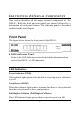
I DENTIFYING E XTERNAL C OMPONENTS This section identifies all the major external components of the DSS-8+. Both the front and rear panels are shown followed by a description of each panel feature. The indicator panel is described in detail in the next chapter. Front Panel The figure below shows the front panel of the DSS-8+. ♦ LED Indicator Panel Refer to the LED Indicator section for detailed information about each of the DSS-8+’s LED indicators.
duplex (FDX) mode. Otherwise, it is blinking when collisions are occurring on the respective port. 100M Link/Activity, 10M Link/Activity (100M LINK/ACT(green), 10LINK/ACT(amber)) This indicator lights green when the port is connected to a 100Mbps Fast Ethernet station, if the indicator blinking green will be transmission or received data on the 100Mbps network.
another hub or an Ethernet switch, you should use a crossover cable, or make the connection using the MDI-X jack (described below). ♦ Uplink Jack(s) (MDI-II): Use this jack to connect stations to the hub. This is an MDI-II (Medium-dependent Interface, straightwired) jack, which means you can connect the hub to a device with an MDI-X port using an ordinary straight-through cable, making a crossover cable unnecessary.
C ONNECTING T HE DSS-8+ This chapter describes how to connect the DSS-8+ to your Fast Ethernet network. In each of the following figures, the DSS-8+ is shown. PC to DSS-8+ A PC can be connected to DSS-8+ via a two-pair Category 3, 4, 5 UTP/STP straight cable. The PC (equipped with a RJ-45 10/100Mbps phone jack) can be connected to any of the 8 ports (1x - 8x). The LED indicators for PC connection depend on the LAN card’s capabilities.
A. 10BASE-T Hub For a 10BASE-T hub, the DSS-8+ LED indicators should light up as the following: “Full-Duplex/Collision” indicator is OFF. “100LINK/ACT,10LINK/ACT LED” indicator is light amber. B. 100BASE-TX Hub For a 100BASE-TX hub, the DSS-8+ LED indicators should light up as the following: “Full-Duplex/Collision” LED indicator is OFF. “100LINK/ACT,10LINK/ACT” LED indicator is light green.
A. Using straight cable When using straight cable, this is done from the uplink (MDI-II) port of the DSS-8+ (DSS-8+ A) to any of the 10Mbps or 100Mbps (MDIX) port of the other switch (switch B) or other devices. B. Using crossover cable When using crossover cable, this is done from any (MDI-X) port of the DSS-8+ (DSS-8+ A) to any of the 10Mbps, 100Mbps (MDI-X) port of the other switch (switch B) or other devices. 1.
INSTRUCTIONS FOR USE OF STACKING BRACKETS First, make sure you have one pair of stacking brackets for each device. Next, slide one bracket onto each end of the device as shown in the diagram below. Be sure each bracket is positioned correctly. Note when clicking each bracket into place, the round feet on the bottom of the device will line up with the round holes on the bracket. The brackets are designed to fit snugly in place. Please do not force them. The brackets are now ready for stacking devices.
RJ-45 P IN S PECIFICATION When connecting your DSS-8+ to another switch, a bridge or a hub, a modified crossover cable is necessary. Please review these products for matching cable pin assignment. The following diagram and tables show the standard RJ-45 receptacle/connector and their pin assignments for the switch-tonetwork adapter card connection, and the straight / crossover cable for the DSS-8+-to-switch/hub/bridge connection.
The standard RJ-45 receptacle/connector The following shows straight cable and crossover cable connection: Straight cable for DSS-8+ (uplink MDI-II port) to switch/Hub or other devices connection Crossover cable for DSS-8+ (MDI-X port) to switch/hub or other network devices (MDI-X port) connection 15
T ECHNICAL S PECIFICATIONS General Standards IEEE 802.3 10BASE-T Ethernet IEEE 802.3u 100BASE-TX Fast Ethernet ANSI/IEEE Std. 802.3 NWay Auto-negotiation Protocol CSMA/CD Data Transfer Rate Ethernet: 10Mbps (half duplex), 20Mbps (full-duplex) Topology Star Network Cables 10BASET: 2-pair UTP Cat. 3,4,5 (100 m), EIA/TIA- 568 100-ohm STP (100 m) Fast Ethernet: 100Mbps (half duplex), 200Mbps (full- duplex) 100BASE-TX: 2-pair UTP Cat.
Physical and Environmental DC inputs DC7.5V/1.5A Power Consumption 11.25 watts. (max.
FCC Certifications This equipment has been tested and found to comply with the limits for a Class B digital device, pursuant to Part 15 of the FCC Rules. These limits are designed to provide reasonable protection against harmful interference in a residential installation. This equipment generates, uses and can radiate radio frequency energy and, if not installed and used in accordance with the instructions, may cause harmful interference to radio communications.
LIMITED WARRANTY D-Link provides this limited warranty for its product only to the person or entity who originally purchased the product from D-Link or its authorized reseller or distributor.
Limited Software Warranty: D-Link warrants that the software portion of the product (“Software”) will substantially conform to D-Link’s then current functional specifications for the Software, as set forth in the applicable documentation, from the date of original delivery of the Software for a period of ninety (90) days (“Warranty Period”), if the Software is properly installed on approved hardware and operated as contemplated in its documentation.
Office and, if requested, provide written proof of purchase of the product (such as a copy of the dated purchase invoice for the product) before the warranty service is provided. After an RMA number is issued, the defective product must be packaged securely in the original or other suitable shipping package to ensure that it will not be damaged in transit, and the RMA number must be prominently marked on the outside of the package.
FOR A PARTICULAR PURPOSE AND NON-INFRINGEMENT. IF ANY IMPLIED WARRANTY CANNOT BE DISCLAIMED IN ANY TERRITORY WHERE A PRODUCT IS SOLD, THE DURATION OF SUCH IMPLIED WARRANTYSHALL BE LIMITED TO NINETY (90) DAYS. EXCEPT AS EXPRESSLY COVERED UNDER THE LIMITED WARRANTY PROVIDED HEREIN, THE ENTIRE RISK AS TO THE QUALITY, SELECTION AND PERFORMANCE OF THE PRODUCT IS WITH THE PURCHASER OF THE PRODUCT.
Trademarks Copyright 1999 D-Link Corporation. Contents subject to change without prior notice. D-Link is a registered trademark of D-Link Corporation/D-Link Systems, Inc. All other trademarks belong to their respective proprietors. Copyright Statement No part of this publication may be reproduced in any form or by any means or used to make any derivative such as translation, transformation, or adaptation without permission from D-Link Corporation/D-Link Systems Inc.