DSS-5+ 5-port 10/100Mbps Switch User’s Guide Rev. 03 (MAR.
TABLE OF C ONTENTS TABLE OF CONTENTS ................................... I ABOUT THIS GUIDE .................................... III PURPOSE ............................................................... III TERMS/USAGE ....................................................... III OVERVIEW OF THIS USER’S GUIDE ............................ III INTRODUCTION .............................................. 1 FAST ETHERNET TECHNOLOGY .................................. 1 SWITCHING TECHNOLOGY.....................
PORT SPEED & DUPLEX MODE .................................. 9 TECHNICAL SPECIFICATIONS.................
A BOUT T HIS G UIDE Congratulations on your purchase of the 5-Port 10/100M Switch. This device integrates 100Mbps Fast Ethernet and 10Mbps Ethernet network capabilities in a highly flexible desktop package. Purpose This manual discusses how to install your 5-Port 10/100M Switch. Terms/Usage In this guide, the term “Switch” (first letter upper case) refers to your 5-Port 10/100M Switch, and ”switch” (first letter lower case) refers to other Ethernet switches. Overview of this User’s Guide Introduction.
I NTRODUCTION This chapter describes the features of the Switch and some background information about Ethernet/Fast Ethernet switching technology. Fast Ethernet Technology The growing importance of LANs and the increasing complexity of desktop computing applications are fueling the need for high performance networks. A number of highspeed LAN technologies have been proposed to provide greater bandwidth and improve client/server response times.
Switching Technology Another approach to pushing beyond the limits of Ethernet technology is the development of switching technology. A switch bridges Ethernet packets at the MAC address level of the Ethernet protocol. It transmits packets among connected Ethernet or Fast Ethernet LAN segments. Switching is a cost-effective way of increasing the total network bandwidth available to users on a local area network. A switch divides a local area network into multiple, separate segments.
Switching LAN technology is a marked improvement over the previous generation of network bridges, which were characterized by higher latencies. Today switches are an ideal solution to most kinds of local area network congestion problems. Features The DSS-5+ was designed for easy installation and high performance in an environment where network traffic and the number of users increases continuously. Designed with the small and medium network in mind, the DSS-5+ comes in a small and compact size.
The Switch is an unmanaged 10/100 Fast Ethernet Switch that offers solutions in accelerating small Ethernet workgroup bandwidth. Other key features are: Auto-MDI (media dependent interface) port supports automatic MDI/MDIX crossover detection function gives true ‘plug and play’ capability without the need of confusing crossover cables or crossover ports. Store and forward switching scheme capability.
U NPACKING AND S ETUP This chapter provides unpacking and setup information for DSS-5+. Unpacking Open the shipping cartons of the Switch and carefully unpacks its contents. The carton should contain the following items: One DSS-5+ 5-port 10/100Mbps Switch One external power adapter This User’s Guide If any item is found missing or damaged, please contact your local reseller for replacement. Setup The setup of DSS-5+ can be performed using the following steps: The surface must support at least 1.
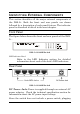
I DENTIFYING E XTERNAL C OMPONENTS This section identifies all the major external components of the DSS-5+. Both the front and rear panels are shown followed by a description of each panel feature. The indicator panel is described in detail in the next chapter. Front Panel The figure below shows the front and rear panels of the DSS5+ . DSS-5+ 10/100M Switch LED Indicator Panel Refer to the LED Indicator section for detailed information about each of the hub’s LED indicators.
its power adapter into a power outlet will immediately power it on. Auto-MDI Jacks: These jacks supports automatic MDI/MDIX crossover detection function gives true ‘plug and play’ capability without the need of confusing crossover cables or crossover ports. With the Auto-MDI function, you just need to plug-in the network cable to the hub directly and no need to care if the end node is NIC (Network Interface Card) or switches and hubs.
C ONNECTING T HE S WITCH This chapter describes how to connect the DSS-5+ to your Fast Ethernet network. PC to Switch A PC can be connected to the Switch via a two-pair Category 3,4, or5 UTP/STP straight-through cable. For 100Mbps operation Category 5 must be used. The PC (equipped with a RJ-45 10Mb Ethernet or 100Mb Fast Ethernet NIC) should be connected to any of the 5 ports (1x - 5x) for the DSS-5+. The LED indicators for PC connection are dependent on the LAN card capabilities.
(switch B) or other devices.
T ECHNICAL S PECIFICATIONS General Standards IEEE 802.3 10Base-T Ethernet IEEE 802.3u 100 Base-TX Fast Ethernet ANSI/IEEE Std 802.3 NWay auto-negotiation IEEE 802.3x Full duplex Flow Control Protocol CSMA/CD Data Transfer Rate Ethernet: 10Mbps (half duplex) 20Mbps (full duplex) Fast Ethernet: 100Mbps (half duplex) 200Mbps (full duplex) Topology Star Network Cables 10BASET: 2-pair UTP Cat. 3,4,5 (100 m), EIA/TIA568 100-ohm STP 100BASE-TX: 2-pair UTP Cat.
Physical and Environmental DC inputs 7.5VDC/1A Power Consumption 7.5 watts. (max.
FCC Certifications This equipment has been tested and found to comply with the limits for a Class B digital device, pursuant to Part 15 of the FCC Rules. These limits are designed to provide reasonable protection against harmful interference in a residential installation. This equipment generates, uses and can radiate radio frequency energy and, if not installed and used in accordance with the instructions, may cause harmful interference to radio communications.
LIMITED WARRANTY D-Link provides this limited warranty for its product only to the person or entity who originally purchased the product from D-Link or its authorized reseller or distributor.
Limited Software Warranty: D-Link warrants that the software portion of the product (“Software”) will substantially conform to D-Link’s then current functional specifications for the Software, as set forth in the applicable documentation, from the date of original delivery of the Software for a period of ninety (90) days (“Warranty Period”), if the Software is properly installed on approved hardware and operated as contemplated in its documentation.
(such as a copy of the dated purchase invoice for the product) before the warranty service is provided. After an RMA number is issued, the defective product must be packaged securely in the original or other suitable shipping package to ensure that it will not be damaged in transit, and the RMA number must be prominently marked on the outside of the package. The packaged product shall be insured and shipped to D-Link, 53 Discovery Drive, Irvine CA 92618, with all shipping costs prepaid.
WHERE A PRODUCT IS SOLD, THE DURATION OF SUCH IMPLIED WARRANTYSHALL BE LIMITED TO NINETY (90) DAYS. EXCEPT AS EXPRESSLY COVERED UNDER THE LIMITED WARRANTY PROVIDED HEREIN, THE ENTIRE RISK AS TO THE QUALITY, SELECTION AND PERFORMANCE OF THE PRODUCT IS WITH THE PURCHASER OF THE PRODUCT.
No part of this publication may be reproduced in any form or by any means or used to make any derivative such as translation, transformation, or adaptation without permission from D-Link Corporation/D-Link Systems Inc., as stipulated by the United States Copyright Act of 1976.