
User`s guide


XStack Storage User’s Guide xi
List of Figures
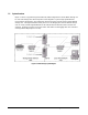
Figure 1-1 XStack Storage System Diagram............................................................19
Figure 2-1 Internal Structure of a Volume.............................................................26
Table 2-2 Ways to Organize Volumes...................................................................26
Figure 3-1 Front View of the XStack DSN-3000 Series Enclosure...................................32
Table 3-1 Front Panel LED indicators on the DSN-3000 series enclosure .........................33
Figure 3-2 Drive and Tray Removal .....................................................................34
Figure 3-3 Drive and Tray Installation..................................................................35
Figure 3-4 Rear View of the XStack DSN-3200 Enclosure............................................36
Figure 3-5 Power and Reset Switches ..................................................................36
Figure 3-6 External Interfaces on the XStack DSN-3200 Enclosure ................................37
Figure 3-8 External Interfaces on the XStack DSN-3400 Enclosure ................................39
Figure 4-1 Battery Pack Installed on XStack Controller .............................................51
Figure 4-2 Power Supply..................................................................................52
Figure 4-3 Power-On Switch and Reset Switch Located on Rear of Enclosure ...................53
Figure 5-1 XStack Storage Log in Screen...............................................................56
Figure 5-2 XStack Storage Management Console Main Screen......................................57
Figure 5-3 Parts of the XStack Storage Management Console Main Screen.......................58
Figure 5-4 Menu/Tool Bar Area..........................................................................59
Figure 5-5 Resources Pane ...............................................................................60
Figure 5-6 Main Display Area.............................................................................62
Figure 5-7 Example of the Main Display Area Showing Blade A Base Pool Information.........62
Figure 5-8 Example of Message in the Footer.........................................................63
Figure 5-9 Configure Out of Band Port Dialog Box....................................................65
Figure 5-10 XStack Storage Date and Time Dialog Box ..............................................67
Figure 5-11 Configure Email Notification Dialog Box.................................................68
Figure 5-12 Volume Wizard Screen – Select Volume Type to Create Screen .....................70
Figure 5-13 Volume Wizard Screen – Access and Efficiency Settings Screen.....................71
Figure 5-14 Manual Create Volume Wizard - Select Volume Type to Create Screen............74
Figure 5-15 Manual Create Volume Wizard - Select the Drives Screen............................75
Figure 5-16 Expand Volume Dialog Box ................................................................77
Figure 5-17 Expand Volume Message ...................................................................78
Figure 5-18 Delete Volume Confirmation Message ...................................................79
Figure 5-19 Successful Volume Deletion Message ....................................................79
Figure 5-20 Scan Successfully Started Message .......................................................80
Figure 5-21 Scan Successfully Started Message .......................................................81
Figure 5-22 Add Initiator Wizard – Create Initiator Screen .........................................82
Figure 5-23 Example of Link Aggregation between the XStack Storage and a Gigabit Ethernet
Switch.......................................................................................
84
Figure 5-24 Create Link Aggregation Group Wizard - LAG Parameters Screen...................85
Figure 5-25 Create Link Aggregation Group Wizard - Add/Delete Ethernet Ports Screen......86
Figure 5-26 Modify Lag Parameters Dialog Box .......................................................87
Figure 5-27 Add/Remove Ethernet Ports for LAG Wizard - Add/Delete Ethernet Ports screen88
Figure 5-28 Create Network Portal Wizard – Set the IP Address Screen ..........................91
Figure 5-29 Create iSCSI Node Wizard - Enter iSCSI Node Information Screen...................93
Figure 5-30 Create iSCSI Node Wizard - Enter iSCSI Node Information Screen with CHAP
Secret Field Shown........................................................................
94
Figure 5-31 Create iSCSI Node Wizard - Configure iSCSI Node Parameters Screen..............94
Figure 5-32 Create iSCSI Node Wizard – iSCSI Network Portal Screen.............................95
Figure 5-33 Create iSCSI Node Wizard – Initiator List Screen.......................................96