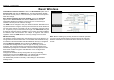
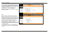
Section 3 – Configuration Basic Wireless To disable the wireless interface: click in the Deactivated option next to Access Point: and click the SAVE button. This will immediately disable the wireless access point; it is not necessary to restart the access point to make this change. If the wireless interface has been disabled: click in the Activated option next to Access Point: and click the SAVE button.
Section 3 – Configuration WEP Encryption WEP (Wireless Encryption Protocol or Wired Equivalent Privacy) encryption can be enabled for security and privacy. WEP encrypts the data portion of each frame transmitted from the wireless adapter using one of the predefined keys. Decryption of the data contained in each packet can only be done if the both the receiver and transmitter have the correct key. By default authentication is disabled on the access point.
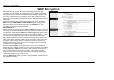
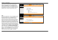
Section 3 – Configuration WPA Settings WPA uses an encryption method combined with an authentication procedure that requires an acceptance of a pre-configured password. WPA or Wireless Protection Access is an improved standard of wireless security. The ROUTER also supports two common encryption types TKIP and AES. To configure WPA settings, select the Authentication Type option WPA-PSK to use TKIP encryption or select WPA2-PSK to use AES encryption.
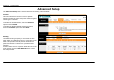
Section 3 – Configuration Advanced Setup The Advanced Setup folder contains windows for Routing, NAT and ADSL. Firewall This menu allows the Router to enforce specific policies intended to protect the private network against certain types of attacks. To enable the firewall feature, select the Enabled option and click SAVE. To enable the Stateful Packet Inspection feature, select the Enabled option and click SAVE.
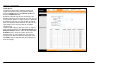
Section 3 – Configuration To add a static route to a specific destination IP on the local network, enter a Destination IP Address, select a suitable IP Subnet Mask, and type in the Gateway IP Address. Click SAVE to enter the new static route in the table below. The route becomes active immediately upon creation. The Metric field determines the number of hops or routers that will be allowed to route traffic.
Section 3 – Configuration Note that if the NAT Status in the window above indicates “Deactivated,” the user must first activate NAT on the Internet menu. Click SAVE and the window above will appear. The IP Address Mapping (for Multiple IP Service) link only appears when the Multiple option is selected under Number of IPs. DMZ Since some applications are not compatible with NAT, the Router supports use of a DMZ IP address for a single host on the LAN.
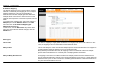
Section 3 – Configuration Virtual Server To customize inbound port mapping of NAT for a Single User Account using one global IP address, select the Single option under Number of IPs and click the Virtual Server link. By default, NAT will map all ports according to the traditional IP NAT protocol. However, the user may opt to map specific ports or a range of ports to a specified IP address on the LAN. It is also possible to map all ports to a specified LAN IP address.
Section 3 – Configuration IP Address Mapping The Router allows the user to setup policies used for inbound or outbound port mapping to one or multiple global IP addresses. This may be desirable on networks that maintain multiple global IP addresses, multiple virtual connections or where servers on the network must respond to connection requests from the WAN.
Section 3 – Configuration QoS Quality of Service or QoS assigns a priority level to data packets to make sure time sensitive network applications operate smoothly with minimal delay. QoS enables applications such as VoIP (voice-over Internet Protocol) or video conferencing to function well on networks that may have multiple simultaneous transmissions of many types of data.
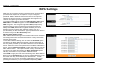
Section 3 – Configuration 802.1p To implement QoS mapping for IEEE 802.1p priority, select the Activated option and configure mapping for the 8 priority levels defined by 802.1p priority. 802.1p user priority 0 is the lowest priority while 7 is the highest. IP QoS To implement QoS mapping for IP QoS, select the Activated option and configure mapping for one of two types of IP QoS, IP ToS (Type of Service) or DiffServ: IP ToS assigns 0 for the lowest priority and 7 for the highest.
Section 3 – Configuration VLAN The Router supports port-based VLANs to segment the Ethernet LAN and/or map 802.1Q VLAN groups to different PVCs. VLANs are grouped according to physical Ethernet port or by PVC for users running multiple connections on the WAN. To use VLANs select the Activated option, then open a separate menu to Assign VLAN PVID for Each Interface. When multiple connections are used on the WAN, this is especially useful to assign VLAN user groups to specified PVCs.
Section 3 – Configuration Assign PVID Enter the desired PVID values in the menu and then click the SAVE button. PVIDs assignment can be used to create port-based VLANs for any of the four Ethernet ports; or use the PVID to map VLANs to separate PVCs. The eight PVCs are labeled ATM VC # 1, VC # 2 and so on up to VC # 7 for the purpose of VLAN to PVC mapping.
Section 3 – Configuration VLAN To define a VLAN group, click Define VLAN Group in the VLAN menu to access the VLAN Group Setting menu. Make the desired VLAN Group assignment and tagging settings in the window above and then click the SAVE button. Up to eight VLAN groups may be created. Click to select the Ethernet Port and ATM VCs Port for each VLAN member port. Any port may be specified as Tagged. Packets that are tagged (are carrying the 802.1Q VID information) can be transmitted from one 802.
Section 3 – Configuration ADSL This menu allows the user to set the configuration for ADSL protocols. For most ADSL accounts the default settings will work. This configuration works with all ADSL implementations. If you have been given instructions to change the ADSL Mode or ADSL Type, select the desired option from the drop-down menus and click the SAVE button.
Section 3 – Configuration Access Management The Access Management directory contains links for the ACL, Filter, SNMP, UPnP, and DDNS menus. ACL Access Control on the Router is an IP-based and/or application-based filtering mechanism used for security and efficiency. Add rules to the list that specify IP address or IP address range. For each rule, a network application can be specified. The Interface effected can be specific to the LAN, WAN or Both. Click the SAVE button to apply and save the new rule.
Section 3 – Configuration Filter Menus The filtering functions on the Router are based on IP address, MAC address, URL or common network applications. Choose the type of filtering to configure and enter the criteria appropriate for that type of filtering. Each menu presents settings specific to the type. IP and MAC based filtering rules can be applied sequentially so that each rule has the option of forwarding packets that do not match the rule, or going to the next rule on the list for further scrutiny.
Section 3 – Configuration Application Filter The Application Filter is a simple filter that drops all incoming packets for the selected applications from the Internet. Choose the applications to Allow or Deny from those listed and click the SAVE button to apply and save the application filtering rule. The application filter can be Activated or Deactivated at any time without changing the selected options.
Section 3 – Configuration The URL Filter will deny access to any URL entered in the list. Up to 16 URLs can be specified. The URL Filter can be Active or not without changing the entries on the list. Select an index number for a new URL to be added to the list, type the URL and click the SAVE button to add it to the list. Remove a URL from the list by choosing the index number for the URL to be removed and clicking on the Delete button.
Section 3 – Configuration SNMP Simple Network Management Protocol is a standard for internetwork and intranetwork management. Enter the desired information in the Get Community and Set Community fields and then click the SAVE button when you are finished with your SNMP settings. UPnP UPnP supports zero-configuration networking and automatic discovery for many types of networked devices.
Section 3 – Configuration DDNS The Router supports Dynamic Domain Name Service or Dynamic DNS. Dynamic DNS is used for account that may not have a permanent fixed global IP address for servers or other resources that are accessed through the Internet. It allows the user to alias a dynamic IP address to a fixed host name. To configure Dynamic DNS: 1. Click the Activated box to select it. 2. Enter the full host and domain name used for your Dynamic DNS under My Host Name. 3.
Section 3 – Configuration Maintentance The Maintenance folder contains windows for Administration, Time Zone, Firmware, SysRestart, and Diagnostics. Password Administration To create a new password, type the new password in the New Password field and then retype it in the Confirm Password field. The Username (admin) used to access the Router’s management software cannot be changed by the user.
Section 3 – Configuration Time Zone The Router provides a number of options to maintain current date and time. To configure system time on the Router, select the method used to maintain time. If you wish to use a network timeserver, select the method used from the Synchronize time with radio buttons and type in the IP address of the NTP Server Address. Select Time Zone and choose Daylight Saving settings where appropriate.
Section 3 – Configuration Firmware Update Firmware Use this window to load the latest firmware for the device. To upgrade firmware, type in the name and path of the file or click on the Browse button to search for the file. Click the UPGRADE button to begin copying the file. The file will load and restart the Router automatically.
Section 3 – Configuration Reset/Restart System SysRestart To reset the Router to its factory default settings, click the SysRestart button in the Maintenance menu. Select the Factory Default Settings radio button under System Restart with and click RESTART. To perform a simple reboot, select System Restart with Current Settings and click RESTART. You will be prompted to wait for the reboot to complete. Click OK to proceed.
Section 3 – Configuration Diagnostics Diagnostics This window is used to test connectivity of the Router. The diagnostic features execute a series of tests of your system software and hardware connections. Use these when working with your ISP to troubleshoot problems.
Section 3 – Configuration Status The Status directory contains Device Info, System Log, and Statistics displays. Device Info This display window is used to view Device, LAN, WAN, and ADSL information.
Section 3 – Configuration System Log This window displays chronological event log data. Use the navigation buttons to view or scroll log pages. You may also save a simple text file containing the log to your computer. Click the SAVE LOG button and follow the prompts to save the file.
Section 3 – Configuration Statistics Use the Traffic Statistics window to monitor traffic on the Ethernet, Wireless or ADSL connection. Select the interface for which you want to view packet statistics and the information will appear below.
Appendix A – Troubleshooting Troubleshooting This chapter provides solutions to problems that might occur during the installation and operation of the DSL-2640R. Read the following descriptions if you are having problems. (The examples below are illustrated in Windows® XP. If you have a different operating system, the screenshots on your computer will look similar to the following examples.) 格式化: 項目符號及編號 1.
Appendix A – Troubleshooting 3. What can I do if my Router is not working correctly? There are a few quick steps you can take to try and resolve any issues: • Follow the directions in Question 2 to reset the Router. • Check that all the cables are firmly connected at both ends. • Check the LEDs on the front of the Router. The Power indicator should be on, the Status indicator should flash, and the DSL and LAN indicators should be on as well.
Appendix B - Networking Basics Networking Basics Check Your IP Address After you install your new D-Link adapter, by default, the TCP/IP settings should be set to obtain an IP address from a DHCP server (i.e. wireless router) automatically. To verify your IP address, please follow the steps below. Click on Start > Run. In the run box type cmd and click on the OK. At the prompt, type ipconfig and press Enter. This will display the IP address, subnet mask, and the default gateway of your adapter.
Appendix B - Networking Basics Statically Assign An IP Address If you are not using a DHCP capable gateway/router, or you need to assign a static IP address, please follow the steps below: Step 1 Windows® XP - Click on Start > Control Panel > Network Connections. Windows® 2000 - From the desktop, right-click on the My Network Places > Properties. Step 2 Right-click on the Local Area Connection which represents your D-Link network adapter and select Properties.
Technical Specifications ADSL Standards • • • • Data Transfer Rate • • • Full-rate ANSI T1.413 Issue 2 ITU G.992.1 (G.dmt) ITU G.992.2 (G.lite) ITU G.994.1 (G.hs) • ADSL2 Standards • ITU G.992.3 (G.dmt.bis) Wireless Transfer Rates IEEE 802.11b: 11, 5.5, 2, and 1Mbps IEEE 802.11g: 6, 9, 12, 18, 24, 36, 48, 54Mbps ADSL2+ Standards • ITU G.992.5 (G.dmt.bisplus) Protocols • • • • • • • • • • IEEE 802.