FCC Notices This device complies with Part 15 of the FCC Rules. Operation is subject to the following two conditions: (1) this device may not cause harmful interference, and (2) this device must accept any interference received, including interference that may cause undesired operation. CAUTION: Change or modification not expressly approved by the party responsible for compliance could void the user’s authority to operate this equipment.
Table of Contents PACKAGE CONTENTS .......................................................................................... 1 SYSTEM REQUIREMENTS ..................................................................................... 1 FEATURES .......................................................................................................... 2 LEDs............................................................................................................. 4 STATUS...................................
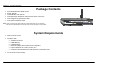
Section 1 - Product Overview Package Contents • • • • • • DSL-2640R Wireless ADSL Router Power Adapter CD-ROM with User Manual One twisted-pair telephone cable used for ADSL connection One straight-through Ethernet cable One Quick Installation Guide Note: Using a power supply with a different voltage rating than the one included with the DSL-2640R will cause damage and void the warranty for this product.
Section 1 - Product Overview 11 Features • • • • • • • • • • PPP (Point-to-Point Protocol) Security – The DSL-2640R ADSL Router supports PAP (Password Authentication Protocol) and CHAP (Challenge Handshake Authentication Protocol) for PPP connections. The Router also supports MSCHAP. DHCP Support – Dynamic Host Configuration Protocol automatically and dynamically assigns all LAN IP settings to each host on your network.
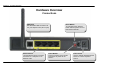
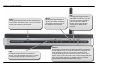
Section 1 - Product Overview Hardware Overview Connections ADSL Port Use the ADSL cable to connect to the your telephone line (RJ-11 port) Ethernet Ports Use the Ethernet ports to connect the Router to a computer or an Ethernet LAN D-Link DSL-2640R User Manual Reset Button To manually reset, depress button with the power on for at least seven seconds Power Button Push in to power-on the Router.
Section 1 - Product Overview Hardware Overview LEDs Power Steady green light indicates the unit is powered on. This remains dark when power is off. A red colored Power LED indicates system failure. LAN A solid green light indicates a valid link on startup. This light will blink when there is activity currently passing through the Ethernet port. D-Link DSL-2640R User Manual WLAN Steady green light indicates a wireless connection. A blinking green light indicates activity on the Wireless LAN interface.
Section 2 – Installation Installation This section will walk you through the installation process. Placement of the Wireless ADSL Router is very important. Do not place the Router in an enclosed area such as a closet, cabinet, or in the attic or garage. Place the Wireless ADSL Router in a location where it can be easily connected to Ethernet devices, the telephone line as well as to a power source.
Section 2 – Installation Web Browser Any common web browser can be used to configure the Router using the web configuration management software. The program is designed to work best with more recently released browsers such as Opera, Microsoft Internet Explorer® version 6.0, Netscape Navigator® version 6.2.3, or later versions. The web browser must have JavaScript enabled. JavaScript is enabled by default on many browsers.
Section 2 – Installation Information you will need from your ADSL service provider Username This is the Username used to log on to your ADSL service provider’s network. Your ADSL service provider uses this to identify your account. Password This is the Password used, in conjunction with the Username above, to log on to your ADSL service provider’s network. This is used to verify the identity of your account.
Section 2 – Installation VPI Most users will not be required to change this setting. The Virtual Path Identifier (VPI) is used in conjunction with the Virtual Channel Identifier (VCI) to identify the data path between your ADSL service provider’s network and your computer. If you are setting up the Router for multiple virtual connections, you will need to configure the VPI and VCI as instructed by your ADSL service provider for the additional connections.
Section 2 – Installation Information you will need about your LAN or computer : Ethernet NIC If your computer has an Ethernet NIC, you can connect the DSL-2640R to this Ethernet port using an Ethernet cable. You can also use the Ethernet ports on the DSL-2640R to connect to other computer or Ethernet devices. DHCP Client status Your DSL-2640R ADSL Router is configured, by default, to be a DHCP server.
Section 2 – Installation Power on Router The Router must be used with the power adapter included with the device. 1. Connect the power adapter to the Power Input (12V AC 1.2A) on the back panel of the Wireless ADSL Router and plug the other end of the power adapter to a wall outlet or power strip. 2. Push the Power Button toggle the power on. 3. The Power LED on the front panel will shine bright green to indicate the device is powered on. 4.
Section 2 – Installation Network Connections Connect ADSL Line Use the ADSL cable included with the Router to connect it to a telephone wall socket or receptacle. Plug one end of the cable into the ADSL port (RJ-11 receptacle) on the rear panel of the Router and insert the other end into the RJ-11 wall socket. If you are using a low pass filter device, follow the instructions included with the device or given to you by your service provider.
Section 3 – Configuration Setup This section will show you how to set up and configure your new D-Link Router using the Web-based configuration utility. Web-based Configuration Utility Connect to the Router To configure the WAN connection used by the Router it is first necessary to communicate with the Router through its management interface, which is HTML-based and can be accessed using a web browser.
Section 3 – Configuration Configure the Router When you successfully connect to the web manager, the main Status menu displays a summary of the current state of the Ethernet LAN and WAN networks. This menu can be accessed at any time using the Status hyperlink. All configuration and management of the Router is done using the web-based management interface pictured in the example.
Section 3 – Configuration Quick Start This chapter is concerned with using your computer to configure the WAN connection. The following chapter describes the various windows used to configure and monitor the Router including how to change IP settings and DHCP server setup. Quick Start To use the Quick Start Wizard, click the RUN WIZARD button and follow the instructions in the pop-up window that appears. The initial window summarizes the setup process. Click the Next button to proceed.
Section 3 – Configuration Quick Start Wizard – Set a Password If you want to change the administrator account password, enter a new password in the first text box, re-type it in the second text box, and click Next. If you wish to return to the previous window during the setup process, click the Back button. Quick Start Wizard - Choose Time Zone Choose the time zone you are in from the pull-down menu and click Next. This sets the system time used for the Router.
Section 3 – Configuration Quick Start Wizard – Select ISP Connection Type Now select the Connection Type used for the Internet connection. Your ISP has given this information to you. The connection types available are Dynamic IP Address, Static IP Address, PPPoE/PPPoA, and Bridge Mode. Each connection type has different settings that are configured in the next Quick Start Wizard window. Select the Connection Type specific to your service and click Next to go to the next Quick Start Wizard window.
Section 3 – Configuration Quick Start Wizard - For Dynamic IP Address connections: 1. If you are instructed to change the VPI or VCI number, type in the correct setting in the available entry fields. Most users will not need to change these settings. The Internet connection cannot function if these values are incorrect. 2. Select the specific Connection Type from the drop-down menu.
Section 3 – Configuration Quick Start Wizard - For Bridge Mode connections: 1. If you are instructed to change the VPI or VCI number, type in the correct setting in the available entry fields. Most users will not need to change these settings. The Internet connection cannot function if these values are incorrect. 2. Select the specific Connection Type from the drop-down menu. The available Bridge Mode connection and encapsulation types are 1483 Bridged IP LLC and 1483 Bridged IP VC-Mux. 3.
Section 3 – Configuration Interface Setup To configure the Router’s basic Internet and LAN configuration settings without running the Quick Start Wizard, click on the Interface Setup link in the Wireless ADSL Router’s opening page. This window is also used to configure the Router for multiple virtual connections (Multiple PVCs). Use the Virtual Circuit drop-down menu to display up to eight configurable profiles for the Internet interface.
Section 3 – Configuration PPPoE/PPPoA To set up a PPPoE or PPPoA connection: Follow the instructions to configure the Router to use a PPPoA or PPPoE for the Internet connection. Make sure you have all the necessary information before you 1. Choose the PPPoA/PPPoE option under ISP in the Encapsulation configure the Internet (WAN) connection. section. 2. Most users will not need to change ATM settings in the ATM VC section.
Section 3 – Configuration 6. Activate or Deactivate the Bridge Interface. 7. Select the correct Connection value in the Connection Setting section. If your account is time-based, that is, if your connection fees are based on the amount of time the Router is actively connected to the Internet, select the Connect On-Demand option and enter an appropriate idle timeout in the entry field provided.
Section 3 – Configuration Dynamic IP Address To configure a Dynamic IP Address WAN connection, follow these steps: 1. Choose the Connection Type from the drop-down menu. This defines both the connection protocol and encapsulation method used for your ADSL service. The available options are 1483 Bridged IP LLC and 1483 Bridged IP VC-Mux. If you have not been provided specific information for the Connection Type setting, leave the default setting. 2.
Section 3 – Configuration Static IP Address To configure a Static IP type connection for the WAN, follow these steps: 1. Choose the Static IP Address option under ISP in the Encapsulation section. 2. The settings in the ATM VC section at the top of the window should not be changed unless you have been instructed to change them. However, if you are instructed to change the VPI or VCI values, type in the values assigned for your account.
Section 3 – Configuration Bridge Mode Follow the instructions below to configure a Bridged connection for the Internet interface. 1. Choose the Bridge Mode option under ISP in the Encapsulation section. 2. The settings in the ATM VC section at the top of the window should not be changed unless you have been instructed to change them. However, if you are instructed to change the VPI or VCI values, type in the values assigned for your account.
Section 3 – Configuration LAN Setup To access the LAN window, click the LAN button in the Interface Setup directory. You can configure the LAN IP address to suit your preference. Many users will find it convenient to use the default settings together with DHCP service to manage the IP settings for their private network. The IP address of the Router is the base address used for DHCP.
Section 3 – Configuration Use the Router for DHCP To use the built-in DHCP server, click the DHCP radio button to Enabled if it has not already selected. The IP Address Pool settings can be adjusted. The Starting IP Address is the lowest available IP address (default = 192.168.1.2). If you change the IP address of the Router, this will change automatically to be 1 more that the IP address of the Router. Type in the Lease Time in the entry field provided.
Section 3 – Configuration Wireless Setup The two essential settings for wireless LAN operation are the SSID and Channel Number. The SSID (Service Set Identifier) is used to identify a group of wireless LAN components. The SSID can be broadcast in order to allow properly configured wireless stations to learn the SSID and join the group. Wireless LAN is enabled by default on the Router. If the wireless access point has been previously disabled you can enable 802.