DSL-302G ADSL Ethernet/USB Modem User’s Guide First Edition (February 2002) 6DSL302G..
Wichtige Sicherheitshinweise 1. Bitte lesen Sie sich diese Hinweise sorgfältig durch. 2. Heben Sie diese Anleitung für den spätern Gebrauch auf. 3. Vor jedem Reinigen ist das Gerät vom Stromnetz zu trennen. Vervenden Sie keine Flüssig- oder Aerosolreiniger. Am besten dient ein angefeuchtetes Tuch zur Reinigung. 4. Um eine Beschädigung des Gerätes zu vermeiden sollten Sie nur Zubehörteile verwenden, die vom Hersteller zugelassen sind. 5. Das Gerät is vor Feuchtigkeit zu schützen. 6.
FCC Warning This device complies with part 15 of the FCC Rules. Operation is subject to the following two conditions: (1) This device may not cause harmful interference, and (2) this device must accept any interference received, including interference that may cause undesired operation. This equipment has been tested and found to comply with the limits for a Class B digital device, pursuant to part 15 of the FCC Rules.
TABLE OF CONTENTS ABOUT THIS USER’S GUIDE........................................................................................................................... 3 INTRODUCTION................................................................................................................................................. 1 MODEM DESCRIPTION AND OPERATION .............................................................................................................. 1 MODEM FEATURES..........................
DSL-302G ADSL Ethernet Modem User’s Guide About This User’s Guide This user’s guide provides instructions on how to install the DSL-302G ADSL Modem and use it to connect a computer (or two computers) to the Internet. If you are using a computer with a functioning Ethernet port, you can use the Quick Installation Guide to quickly establish your ADSL connection and access the Internet.
Introduction This section provides a brief description of the Modem, its associated technologies and a list of Modem features. What is ADSL? Asymmetric Digital Subscriber Line (ADSL) is an access technology that utilizes ordinary copper telephone lines to enable broadband high-speed digital data transmission and interactive multimedia applications for business and residential customers. For ADSL services, it is not necessary expensive new cabling or condition the line in any way.
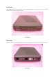
Front Panel Place the Modem in a location that allows a view of the LED indicators. To save space you can use the feet to stand the device on either its right or left side. Front Panel Rear Panel All cable connections to the Modem are made at the rear panel. The factory reset button is located here as well.
LED Indicators LED Indicators The LED Indicators read as follows: Power Steady green light indicates the unit is powered on. Status Lights steady green during the ADSL negotiation phase & connection stage. ADSL: Link Steady green light indicates a valid ADSL connection. This will light after the ADSL negotiation process has been settled. ADSL: Act Blinking green light indicates an active WAN session. Ethernet: Link Steady green light indicates a valid Ethernet connection.
Hardware Installation This chapter describes the various network cable and power connections required to use the Modem. Modem Location When selecting the location for the Modem be sure to allow room to access the connections on the rear panel. You will want to place the Modem so that you will be able to see the LED indicators on the front panel. Allow some space above the Modem for ventilation to avoid problems with overheating.
Software Installation In order to install the software driver for the Modem, you first need to install the DSL-300 Configuration Utility, D-Link’s GUI based management software. This software can later be used to monitor the device or change its settings. Install the Configuration Utility software on the PC directly connected to the device via either the Ethernet or USB interface. In order to install the Configuration Utility on a computer using the USB interface, two additional drivers must be installed.
3. The User Information window asks you for your name and company name. Enter this information in the appropriate field and click Next. 4. In the Choose Destination Location window you may accept to install the Configuration Utility in the automatically chosen directory by clicking Next. Or you can click Browse if you wish to select a different directory. 5.
6. The Start Copying Files window provides an opportunity to review the information you have just entered. If you are satisfied with the information as it is listed, click Next. If you need to change any of the information click Back to go to the previous window(s) to make the changes. 7. In the Setup Complete window you are presented with the option to launch the Configuration Utility program.
A Configuration Utility icon should now be seen on your desktop screen.
Configure the Modem With the Configuration Utility software installed, you are ready to configure the Modem. You must enter the VPI and VCI values that have been given to you by your ADSL service provider to define the path of connection to the ATM network backbone. Click the Configuration Utility icon to initiate the configuration of the Modem. The Configuration Utility will locate the Modem on your LAN. 1.
Type in these numbers in the ADSL Setting field and click Finish. 4. The Save configuration and restart system window will appear. You will be asked if you would like to save the changes you have made (the VPI and VCI numbers) and restart the Modem. Click Yes if you have correctly entered the necessary information. 5. The final window, Configuration saved, confirms that you have made changes to the configuration of the Modem and restarted it. If you wish to close the Configuration Utility, click Yes.
Install the USB Driver To install the USB driver for a computer-attached configuration with a computer running a Windows operating system, follow the procedure below. 1. Plug the USB connector to the DSL-302G, then the Add New Hardware Wizard dialog box is displayed showing the type of USB device that has booted up: 2. Click on Next to continue. The following dialog box is displayed asking you to specify how to install the driver: 3. Ensure that the first option is selected and click on Next.
4. Insert the PC Driver install disk. 5. Check the Floppy disk drive option and click on Next. The following dialog box is displayed which confirms that a suitable driver has been found on the floppy disk which will now be installed: 6. Click on Next to begin the installation of the driver. When the installation has finished, the following dialog box is displayed: 7. Click on the Finish button to complete the installation. The PC Driver for the USB device is now installed.
Installing the PC (Ethernet Client) Driver To install the PC (Ethernet Client) driver for a PC-attached configuration on a PC running Windows 98 SE/Windows 2000, follow the procedure below: Note: If you have just installed the PC (USB) driver for a PC-attached Modem configuration, this procedure will automatically follow on from either of these procedures. The PC having initially detected the DSL-302G as a PC-attached USB device will now detect the DSL-302G as an Ethernet device.
4. Insert the PC Driver install disk. 5. Check the Floppy disk drive option and click on Next. The following dialog box is displayed which confirms that a suitable driver has been found on the floppy disk which will now be installed: 6. Click on Next to begin the installation of the driver. 7. You may be asked to insert the Windows installation CD-ROM that was supplied with your PC. If so, insert the CD and click on Next.
8. Click on the Finish button to complete the installation. The PC driver for the VVB Ethernet port is now installed. 9. You will be asked to restart your computer. Click on Yes to restart the computer. After the reboot, the PC Driver for the Ethernet port will be fully installed. Refer to the next section to configure the driver. Configure the Ethernet Client Driver To configure the Ethernet Client driver, follow the procedure below: 1.
4. Click on the Internet Protocol item in the list box. 5. Click on the Properties button. The Internet Protocol (TCP/IP) Properties window is displayed: 6. Enter the details of the DSL-302G in the Use the following IP address group box: IP address Subnet mask Default gateway 7. Click on OK. 8. Click on OK again to close the remaining open dialog box. The Ethernet Client driver has now been configured.
Modem Diagnostics The Configuration Utility can be used to monitor the activity and performance of the Modem. The four status windows are read-only with the exception of the General ADSL Information. Once you have set the VCI and VPI values there should not be any need to change them. You can choose the interval in which the statistics are refreshed from the pull-down menu on the bottom of the window. Clicking on the ADSL Status tab provides information about the status of the ADSL link and the data.
The General ADSL Information menu displays information on packets received and transmitted via the ADSL line as well as the ADSL settings. This is where you can change the VCI and VPI values, as described in the previous section. The Ethernet Information menu provides information about packets received and transmitted via the Ethernet interface. The Version Information menu lists the current device driver, firmware version and hardware version.
The Advanced ADSL Information menu lists information about errors, signal characteristics and loop distance.
A Technical Specifications General Standards: ITU G.992.1 (G.dmt) ITU G.992.2 (G.lite) ITU G.994.1 (G.Hs) ANSI T1.413 (Issue 2) Protocol: TCP/IP Data Transfer Rate: G.dmt full rate: Downstream up to 8 Mbps Upstream up to 640 Kbps G.lite: Downstream up to 1.
B DSL-302G Firmware Upgrade Utility You can update system firmware using the DSL-302G Firmware Upgrade Utility. To upgrade the Modem’s firmware you must have installed this software on the PC you wish to use for this purpose. Install the utility by clicking the self-executing file setup.exe located on the Installation CD-ROM. It will be installed automatically.
In the new window, you will see the MAC address of the Modem and the IP address of the PC you are using. The PC and the Modem must be on the same subnet for the upgrade to be completed. The upgrade utility will suggest a new IP address to be temporarily assigned to the device during the firmware upgrade procedure. Check the suggested IP address listed for the Modem to be sure that it does not conflict with any existing IP addresses on your network.
D-Link Systems, Inc. (“D-Link”) provides this limited warranty for its product only to the person or entity who originally purchased the product from D-Link or its authorized reseller or distributor.
the foregoing requirements, or that is determined by D-Link not to be defective or non-conforming.