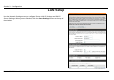
Section 3 – Configuration LAN Setup Use the Network Settings menu to configure Router LAN IP Settings and DHCP Server Settings. When you are finished, click the Save Settings button at the top of the window.
Section 3 – Configuration Router IP Settings Router Settings This section is used to configure the internal network settings of the Router. This IP address is private to your internal network and cannot be seen on the Internet. The default Router IP Address is 192.168.0.1 and the Default Subnet Mask is 255.255.255.0. The Local Domain Name is for the local Domain set on your network, if you have given it a name previously.
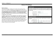
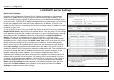
Section 3 – Configuration LAN DHCP Server Settings DHCP Server Settings Dynamic Host Configuration Protocol (DHCP) allows the gateway to automatically obtain the IP address from a DHCP server on the service provider’s network. The service provider assigns a global IP address from a pool of addresses available to the service provider. Typically the IP address assigned has a long lease time, so it will likely be the same address each time the Router requests an IP address.
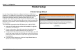
Section 3 – Configuration Printer Setup Printer Setup Wizard Use the Printer Setup Wizard to configure the Router’s USB Printer connection. To establish the connection to a USB equipped printer, click the Printer Setup link to view the Printer Setup Wizard launch menu. Follow the instructions below to install the printer driver on your computer. Some printers, especially very recent release printers, might require the Printer CD-ROM containing the printer driver that came with the printer.
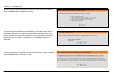
Section 3 – Configuration The first Printer Setup Wizard menu lists the steps used for intallation. Click the Next button to detect the printer. The printer should be detected immediately. The model name will be displayed if detected. If no printer is detected a warning tells you the printer installation cannot be completed. Check the cable connections and make sure the printer is powered on. Click Next if a printer is detected. It is now necessary to install the correct printer driver on your computer.
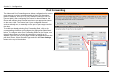
Section 3 – Configuration A setup will launch or attempt to launch on your computer. Often the browser settings prevent the file from launching until permission is granted. This file must be executed to install the printer driver. In Windows Internet Explorer permission can be granted to launch downloded application. See the example from Windows Internet Explorer as seen in XP below.
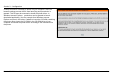
Section 3 – Configuration Time and Date The system time is the time used by the DIR-320 for scheduling services. You can configure, update, and maintain the time on the internal system clock. To configure system time on the Router, select the method used to maintain time. The options available include the default Automatically synchronize with D-Link’s Internet timeserver using Simple Network Time Protocol (SNTP), to use your computer’s system clock, deselect the Automatic option and click the Sync.
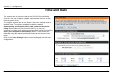
Section 3 – Configuration Parental Control Use this menu to deny access to specified websites and to set Internet access time periods. URL or Uniform Resource Locator is a specially formatted text string that uniquely defines an Internet website. This menu will allow users to block computers on the LAN from accessing certain URLs. To configure this menu for URL blocking, enter the website’s address into the Website URL field, select the desired Schedule and click the Add New button for that entry.
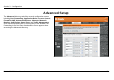
Section 3 – Configuration Advanced Setup The Advanced directory tab offers several configuration menus including Port Forwarding, Application Rules, Access Control, Firewall & DMZ, Advanced Wireless, Advanced Network, Routing, QoS Engine, Guest Zone, and Traffic Management. Click the corresponding link in the left panel of the window. Port Forwarding is the first menu listed and the first to appear when accessing the Advanced directory.
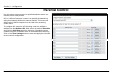
Section 3 – Configuration Port Forwarding The Advanced Port Forwarding menu allows configuration for remote users access to various services outside of their LAN through a public IP address, such as FTP (File Transfer Protocol) or HTTPS (Secure Web). After configuring the Router for these features, the Router will redirect these external services to an appropriate server on the users LAN.
Section 3 – Configuration Application Rules Use the Application Rules menu to configure applications that require multiple connections, such as Internet Telephony, video conferencing, and Internet gaming. The following window lists six Special Applications that commonly use more than one connection. To configure one of these applications, tick its corresponding checkbox and then modify the fields listed below the following figure.
Section 3 – Configuration Access Control Access Control, or MAC filtering, is a basic security measure that should be used on any network that is exposed to a security risk. A packet filter system examines data packets and scrutinizes them in order to control network access. Filtering rules determine whether packets are passed through the Router from either side of the gateway. The rules are created and controlled by the network administrator and can be precisely defined.
Section 3 – Configuration Firewall & DMZ The Firewall & DMZ menu is used to define enforce specific predefined policies intended to protect against certain common types of attacks. A DoS "denial-of-service" attack is characterized by an explicit attempt by attackers to prevent legitimate users of a service from using that service.
Section 3 – Configuration Advanced Wireless The Advanced Wireless menu is used to configure settings that can increase the performance of your router. Click Save Settings when you have completed your changes. See the table below for descriptions of the advanced wireless settings parameters.
Section 3 – Configuration Performance Parameter Description Transmit power Allows the user to adjust the transmit power of the router. A high transmit power allows a greater area range of accessibility to the router. When multiple overlapping access points are present, it may be desirable to reduce transmission power. Beacon Interval Beacons are emitted from the router in order to synchronize the wireless network. You may set the Beacon Interval range between 20-100 microseconds per beacon sent.
Section 3 – Configuration Advanced Network The Advanced Network Settings menu is used to disable or enable UPnP, disable Ping responses on the WAN port and change WAN port speed. UPnP UPnP supports zero-configuration networking and automatic discovery for many types of networked devices. When enabled, it allows other devices that support UPnP to dynamically join a network, obtain an IP address, convey its capabilities, and learn about the presence and capabilities of other devices.
Section 3 – Configuration Gaming Mode When gaming mode is enabled, the router’s QoS settings are adjusted automatically to accommodate Internet gaming. Gaming mode is enabled by default. Multicast Streams Wireless enhanced mode is used to optimize traffic parameters for wireless clients. Routing Use Static Routing to specify a route used for data traffic within your Ethernet LAN or to route data on the WAN.
Section 3 – Configuration QoS Engine Some broadband service providers allow subscribers to adjust Quality of Service (QoS) settings to optimize the Internet connection for VoIP and other time sensitive network applications. If your ISP allows this, enable QoS bandwidth adjustment by clicking to select the Lag eliminated box and adjust the Uplink and Downlink speed using the pull-down menus. Click the Save Settings button to implement the new QoS changes.
Section 3 – Configuration Guest Zone The Guest Zone feature of the router allows an additional subnet to be added. This is especially useful for placing wireless stations in an IP subnet separate from wired Ethernet stations. The four Ethernet ports can also be configured to use the Guest Zone so one or more Ethernet ports can be on a separate IP subnet. To use a guest zone, click to select the Enable Guest Zone box, if desired select a schedule when the Guest Zone is effective.
Section 3 – Configuration Routing between the guest zone and the original host subnet can be enabled by clicking the Enable Routing Between Zones box. If this option is not selected, the two subnets will behave as separate networks with access to the Internet connection, but not to computers on the other subnet. The DHCP server for the guest zone is configured exactly the same as the DHCP server to the original host zone. DHCP clients on the guest zone are listed below the DHCP server setup menu.
Section 3 – Configuration Traffic Management The Traffic Management is used to control Internet connection bandwidth for individual computers on the wired or wireless network. Up to 26 clients can be added to the list for bandwidth control.
Section 3 – Configuration Maintenance The menus of the Maintenance directory include Device Administration, Save and Restore, Firmware Update, DDNS Setting, System Clock, Schedules and Log Settings. Device Administration The Device Administrator menu is used to change the administrator’s login name and password as well as remote management set up. To change the login name or password, enter the new Login Name and password into the New Password field and repeat the password in the Confirm Password field.
Section 3 – Configuration Save and Restore Current system settings can be saved as a file onto the local hard drive by clicking the Save button. The saved file or any other saved setting file can be loaded back on the Router. To reload a system settings file, click on Browse to browse the local hard drive and locate the system file to be used. You may also reset the Router back to factory settings by clicking on Restore Device.
Section 3 – Configuration Firmware Update View the version of the currently loaded firmware and update the system firmware with the Firmware Update menu. Make sure the firmware you want to use is on the local hard drive of the computer. Click on Browse to browse the local hard driver and locate the firmware to be used for the update. Please check the D-Link support site for firmware updates at D-Link Technical support website of your country.
Section 3 – Configuration DDNS Setting The DIR-320 supports DDNS or Dynamic Domain Name Service. Dynamic DNS allows a dynamic public IP address to be associated with a static host name in any of the many domains, allowing access to a specific host from various locations on the Internet. With this function enabled, remote access to a host will be allowed by clicking a URL hyperlink in the following form: dlinkddns.
Section 3 – Configuration System Check This menu is used to monitor port performance and connectivity, the menus displayed are VCT Info and Ping Test. VCT Info The Virtual Cable Tester displays the current status of all ports. Ping Test The Ping Test section allows you to ping any IP address from the Router to test connectivity to the address. To Ping a device, enter the IP address of the device that you wish to ping into the Host Name or IP Address field and click Ping to start the Ping mechanism.
Section 3 – Configuration Schedules This window is used to create implementation schedules. This is the same menu accessed using the Make New Schedule button in the rules menu of various settings pages. Schedule rule setup menu Complete the Add Schedule Rule settings on the window above and then click the Save Settings button at the top of the window.
Section 3 – Configuration Log Settings The system log displays chronological event log data, including System Activity, Debug Information, Attacks, Dropped Packets, and Notice. Check the desired category of Log Type in the bottom half of the window above and then click the Save button and follow the prompts to save the file. Alerts can be sent to an email account. Use the Send By Mail settings to configure Email account information.
Section 3 – Configuration Status The Status directory menus are used to check information about the Router, including Device Information, Log, Statistics, and Active Session. Device Information The Device Information display is used to view information regarding the settings of the Router, both on the LAN side and WAN side of the connection. The firmware version is also displayed here as well as in the firmware upgrade menu.
Section 3 – Configuration Log The Log displays events occurring within the router by time and date, and also view the source and destination of the event. The user may use the First Page, Last Page, Previous and Next buttons to scroll through the log events listed in the window. To clear the log events, click Clear. Click the Link to Log Settings button to change what events are displayed in the log.
Section 3 – Configuration Statistics The Statistics displays shows transmitted and received packets occurring on the Router. To refresh the window, click Refresh. To restart the packet count, click Reset.
Section 3 – Configuration Active Session Source and Destination packets passing through the Router are displayed listed by TCP/UDP type in the Active Session display. To refresh the window, click the Refresh button.
Section 3 – Configuration Wireless Client List The Connected Wireless Client List displays all wireless clients currently connected and the mode of the connection.
Appendix – Technical Specifications Technical Specifications Modulation Technology Standards • IEEE 802.11g • IEEE 802.11b • IEEE 802.3 • IEEE 802.3u 802.11g Wireless Signal Rates* • • • • • • 54 Mbps 36 Mbps 18 Mbps 11 Mbps 6 Mbps 2 Mbps • • • • • • 48 Mbps 24 Mbps 12 Mbps 9 Mbps 5.5 1 Mbps Security • WPA - Wi-Fi Protected Access (TKIP, MIC, IV Expansion, Shared Key Authentication) 802.
Appendix – Technical Specifications VPN Pass Through/ Multi-Sessions • PPTP • L TP • IPSec Device Management • Web-based Internet Explorer v6 or later; Netscape • Navigator v6 or later; or other Java-enabled browsers • DHCP Server and Client Input: DC 5V 2A Operating Temperature 32°F to 131°F ( 0°C to 55°C) Advanced Firewall Features • NAT with VPN Pass-through (Network Address Translation) • MAC Filtering • IP Filtering • URL Filtering • Domain Blocking • Scheduling D-Link DIR-320
Appendix – Technical Specifications Humidity 95% maximum (non-condensing) Safety and Emissions FCC LEDs • Power • Status • Internet • WLAN (Wireless Connection) • LAN (10/100) • USB D-Link DIR-320 User Manual Dimensions L = 5.6 (142mm) W = 4.3 (109mm) H = 1.2 inches (31mm) Weight 7.8 oz (0.
Appendix – Technical Specifications Web-based management function navigator SETUP ADVANCED MAINTENANCE STATUS HELP Internet Setup Port Forwarding Device Administration Device Info Menu Wireless Setup Application Rules Save and Restore Logs Logout LAN Setup Access Control Firmware Update Statistics Printer Setup Firewall & DMZ DDNS Setting Active Session Time and Date Advanced Wireless System Check LAN Clients Parental Control Advanced Network Schedules Logout Logout Routing
Appendix – Technical Specifications FCC Warning statement: This equipment has been tested and found to comply with the limits for a Class B digital device, pursuant to part 15 of the FCC rules. These limits are designed to provide reasonable protection against harmful interference in a residential installation. This equipment generates, uses and can radiate radio frequency energy and, if not installed and used in accordance with the instructions, may cause harmful interference to radio communications.