DFE-908x DFE-908 Ethernet/Fast Ethernet Dual-Speed Stackable Hubs User’s Guide Rev. 01 (December, 1997) 6DFE908...
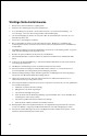
Wichtige Sicherheitshinweise 1. Bitte lesen Sie sich diese Hinweise sorgfältig durch. 2. Heben Sie diese Anleitung für den spätern Gebrauch auf. 3. Vor jedem Reinigen ist das Gerät vom Stromnetz zu trennen. Vervenden Sie keine Flüssig- oder Aerosolreiniger. Am besten dient ein angefeuchtetes Tuch zur Reinigung. 4. Um eine Beschädigung des Gerätes zu vermeiden sollten Sie nur Zubehörteile verwenden, die vom Hersteller zugelassen sind. 5. Das Gerät is vor Feuchtigkeit zu schützen. 6.
WARRANTIES EXCLUSIVE IF THE D-LINK PRODUCT DOES NOT OPERATE AS WARRANTED ABOVE, THE CUSTOMER'S SOLE REMEDY SHALL BE, AT D-LINK'S OPTION, REPAIR OR REPLACEMENT. THE FOREGOING WARRANTIES AND REMEDIES ARE EXCLUSIVE AND ARE IN LIEU OF ALL OTHER WARRANTIES, EXPRESSED OR IMPLIED, EITHER IN FACT OR BY OPERATION OF LAW, STATUTORY OR OTHERWISE, INCLUDING WARRANTIES OF MERCHANTABILITY AND FITNESS FOR A PARTICULAR PURPOSE.
Limited Warranty Hardware: D-Link warrants its hardware products to be free from defects in workmanship and materials, under normal use and service, for the following periods measured from date of purchase from D-Link or its Authorized Reseller: Product Type Complete products Spare parts and spare kits Warranty Period One year 90 days The one-year period of warranty on complete products applies on condition that the product's Registration Card is filled out and returned to a D-Link office within ninety (9
Trademarks Copyright 1997 D-Link Corporation. Contents subject to change without prior notice. D-Link is a registered trademark of D-Link Corporation/D-Link Systems, Inc. All other trademarks belong to their respective proprietors. Copyright Statement No part of this publication may be reproduced in any form or by any means or used to make any derivative such as translation, transformation, or adaptation without permission from D-Link Corporation/D-Link Systems Inc.
FCC Warning &ODVV % IRU 0RGHO ')(0<3;2')(0<3;[ )&& ,' 1R= .
vii
Dual-Speed Stackable Hubs User’s Guide TABLE OF CONTENTS 0 ABOUT THIS GUIDE .......................................................... IX Conventions..........................................................................................ix Overview of the User’s Guide ...............................................................ix 1 INTRODUCTION ................................................................. 1 Product Description ......................................................................
Hub State Indicators............................................................................12 Port State Indicators............................................................................13 Port Speed Indicators ..........................................................................14 Switch Indicator (DFE-908x Only) ......................................................14 4 MAKING CONNECTIONS................................................... 17 Hub Cascading/Building a Stack .................
Dual-Speed Stackable Hubs User’s Guide ABOUT THIS G UIDE This guide discusses how to install and use the DFE-908 series stackable dual-speed Fast Ethernet/Ethernet Hubs. Conventions References in this manual to the DFE-908 and DFE-908x hubs are frequently written simply as “ hub” or “ hubs” where the text applies to all models. Model numbers are normally used only to differentiate between the two where necessary. Unless differentiated by model number, all information applies to all models.
♦ Chapter 4, Making Connections. Provides information on connecting to the hub’s twisted-pair, stacking hubs, and linking with other 100BASE-TX hubs. ♦ Appendix A, Cables and Connectors. Provides specifications on the cables and connectors used with the hubs. ♦ Appendix B, Specifications. Lists the hubs’ specifications.
Dual-Speed Stackable Hubs User’s Guide 1 1 I NTRODUCTION This chapter introduces the DFE-908 series stackable dual-speed Fast Ethernet/Ethernet Hubs, as well as giving some background information about the technology the hubs use. Product Description The D-Link DFE-908 series stackable dual-speed Fast Ethernet/Ethernet Hubs are designed to allow easy migration and integration between 10Mbps Ethernet and 100Mbps Fast Ethernet, while providing flexibility in cable connections.
Class II Fast Ethernet repeater, allowing it to be linked to another Class II Fast Ethernet stack in the same collision domain. On the DFE-908, the 10Mbps and 100Mbps segments are separate and do not intercommunicate. The DFE-908x contains a built-in switch, making it possible to transparently bridge between the 10 Mbps and 100 Mbps segments. Product Features The list below highlights the features and specifications of the DFE-908 series hubs: ♦ Compatible with the IEEE 802.3 10BASE-T Ethernet and 802.
Dual-Speed Stackable Hubs User’s Guide ♦ LED indicators for power, collisions, link, network activity, switch capability (DFE-908x only), partitioning status, operating speed (10 or 100 Mbps) and network utilization. ♦ Auto-partition protection. ♦ Data collision detection and handling. ♦ Preamble regeneration, signal retiming. ♦ Two proprietary daisy-chain ports for cascading up to five hubs to form one logical hub.
repeater retransmits Fast Ethernet transmissions from ports operating at 100Mbps to all other ports operating at the same speed. 10Mbps Repeater 100Mbps Repeater NWay Detection RJ-45 Ports 100Mbps Ethernet Station 100Mbps Ethernet Station 10Mbps Ethernet Station 10Mbps Ethernet Station 100Mbps Ethernet Station If there is a DFE-908x hub present in the stack, its built-in switch serves as a bridge between the two independent segments.
Dual-Speed Stackable Hubs User’s Guide 100BASE-TX Technology Overview 100Mbps Fast Ethernet Introduction Computers today have become increasingly powerful, with the capability to accommodate very sophisticated uses such as multimedia applications, video-conferencing, and CAD/CAM. To utilize these technologically advanced applications more efficiently, there is also a growing demand for faster networks that can handle heavy network traffic.
Topology A Fast Ethernet workgroup is configured in a star topology and is built around a maximum of two repeaters. Each workgroup forms a separate LAN (also known as a segment or collision domain), and these workgroups can be easily interconnected through switches, bridges, or routers to form one LAN large enough to encompass a high-rise building or campus environment.
Dual-Speed Stackable Hubs User’s Guide Hub Types Unlike 10BASE-T hubs, which are all functionally identical, Fast Ethernet hubs are divided into two distinct types: Class I and Class II. A Class I hub repeats all incoming signals on one port to the other ports by first translating them to digital signals and then retranslating them back to line signals.
Unpacking Open the shipping carton of your hub and carefully unpack the contents. The carton should contain the following items: ♦ One dual-speed stackable hub ♦ One AC power cord, suitable for your area’s electrical power connections ♦ One daisy-chain cable ♦ Four rubber feet to be used for shock cushioning ♦ This User’s Guide Inspect the hub and all accompanying items. If any item is damaged or missing, report the problem immediately to your D-Link dealer.
Dual-Speed Stackable Hubs User’s Guide ♦ LED Indicator Panel Refer to the next chapter, Understanding Indicators, for detailed information about each of the hub’s LED indicators. ♦ Twisted-Pair Ports Use any of these ports to connect stations to the hub. The ports are MDI-X ports, which means you can use ordinary straight-through twisted-pair cable to connect the hub to PCs, workstations, or servers through these ports.
Rear Panel ♦ Daisy-Chain IN Port When cascading a set of D-Link’s stackable dual-speed hubs, this port should be connected to the Daisy-Chain OUT port of the previous hub in the stack (usually placed immediately above it). A cascade of five hubs can be created in this way. The first and last hubs in the stack use only one of the daisy-chain ports, while the others use both. ♦ Daisy-Chain OUT Port Works in conjunction with the Daisy-Chain IN Port (see above).
Dual-Speed Stackable Hubs User’s Guide Installing the Hub Installation The site where you install the hub stack may greatly affect its performance. When installing, consider the following pointers: ♦ Install the hub stack in a fairly cool and dry place. See Appendix B, Specifications, for the acceptable temperature and humidity operating ranges. ♦ Install the hub stack in a site free from strong electromagnetic field generators (such as motors), vibration, dust, and direct exposure to sunlight.
3 3 UNDERSTANDING I NDICATORS Before connecting network devices to the hub, take a few minutes to look over this section and familiarize yourself with the front panel LED indicators of your dual-speed hub, depicted below.
Dual-Speed Stackable Hubs User’s Guide This indicator lights green when the hub is receiving power; otherwise, it is off. ♦ Collision Indicators (Col 10M/ Col 100M) These indicators indicate data collisions on the respective 10Mbps Ethernet or 100Mbps Fast Ethernet segments connected to the hub. (If several hubs are stacked or linked together, all of them should detect and indicate the same collision, since collisions span the entire network segment.
♦ Receive (Rx) (blinking green) When information is received on a port, its indicator will blink off briefly. Upon reception, the data will be transmitted to all other connected ports. ♦ Auto-partition (Auto-part) (steady amber) The indicator of a port lights amber when the port is automatically partitioned due to an abnormal network condition. The hub will temporarily partition a port when too many collisions are detected on the port.
Dual-Speed Stackable Hubs User’s Guide Understanding Indicators 15
Dual-Speed Stackable Hubs User’s Guide 4 4 MAKING CONNECTIONS This chapter discusses how to make connections to the hub’s twisted-pair ports, cascading hubs to create a stack, and linking with other hubs (or hub stacks). Hub Cascading/Building a Stack You can stack up to five hubs using the daisy-chain ports to form one logical hub. In this configuration, the interconnected hubs constitute a single logical unit, providing a maximum of 40 twisted-pair ports.
Hubs should not be added to the stack or removed from the stack while the power is on to any hub in the stack. Always turn off power to the entire stack before adding or removing hubs.
Dual-Speed Stackable Hubs User’s Guide ♦ The maximum length of a twisted-pair cable segment is 100 meters. Cabling should be Category 3 or better. ♦ Between any two end-stations in a collision domain, there may be up to five cable segments and four intermediate repeaters (hubs, hub stacks, or other repeaters). ♦ If there is a path between any two end-stations containing five segments and four repeaters, then at least two of the cable segments must be point-to-point link segments (e.g.
Ethernet connection requires a Category 3 or better UTP cable. It is recommended that you use Category 5 cabling for all connections, in order to make it easier to transition all stations to 100Mbps. You can connect any combination of PCs, servers, and other single-address network devices to the eight twisted-pair ports using straight-through twisted-pair cables. These cables should not be crossed over.
Dual-Speed Stackable Hubs User’s Guide Hub-to-Hub Uplink You can link two hubs or hub stacks to each other using any of the twistedpair ports or the Uplink port. Linking hubs using ordinary twisted-pair ports requires crossover twisted-pair cables; linking using one ordinary twisted-pair port and the Uplink port requires an ordinary straight-through twisted-pair cable. The Uplink port is shared with Port 1, and you should not use both Port 1 and the Uplink port at the same time.
The following table describes different methods of linking hubs (or hub stacks): HUB PORT USED DEVICE PORT TYPE CABLE TO USE Normal Switch or Hub NonUplink Uplink Crossover (X) Uplink Straight-Through (||) Server (or PC) Straight-Through (||) Switch or Hub Straight-Through (||) NonUplink Uplink Server (or PC) Crossover (X) Crossover (X) A crossover cable is a straight-through twisted-pair cable in which the wires have been crossed.
Dual-Speed Stackable Hubs User’s Guide A 5 CABLES AND CONNECTORS 100BASE-TX Ethernet Cable and Connectors ♦ Cable characteristics: 0.4 to 0.
Contact 1 2 3 4 5 6 7 8 MDI-X Signal RD+ (receive) RD- (receive) TD+ (transmit) Not used Not used TD- (transmit) Not used Not used MDI Signal TD+ (transmit) TD- (transmit) RD+ (receive) Not used Not used RD- (receive) Not used Not used Crossover Cables When cascading or connecting the hub to another switch, bridge, or hub through the UTP port, a modified crossover cable is necessary. With a crossover cable, two pairs of wires are switched at one connector end.
Dual-Speed Stackable Hubs User’s Guide Cables and Connectors 25
B 6 S PECIFICATIONS General Standards: IEEE 802.3 10BASE-T Ethernet repeater IEEE 802.3u 100BASE-TX Fast Ethernet repeater (Class II) ANSI X3T9.5 Twisted-Pair Transceiver Topology: Star Protocol: CSMA/CD Network Data Transfer Rate: Ethernet: 10Mbps; Fast Ethernet: 100 Mbps Number of Ports per Hub: 8, all dual-speed (10Mbps/100Mbps) Network Cables: 10BASE-T: 2-pair UTP Cat. 3, 4, 5 (100 m); EIA/TIA-568 100-ohm screened twisted-pair (STP) (100 m) 100BASE-TX: 2-pair UTP cat.
Daisy-Chain Port: MiniSCSI-type connector × 2 Daisy-Chain Cable: SCSI-type cable (supplied) LED Indicators Hub Status: Power, 10Mbps collision, 100Mbps collision, 10Mbps utilization, 100Mbps utilization Port Status (per port): Link/Receive/Auto Partition, Speed (10/100Mbps) Environmental and Physical Power Supply: 100 to 240 VAC, 50 or 60 Hz internal universal power supply Power Consumption: DFE-908x: 10 watts max.; DFE-908: 10 watts max. Dimensions: 233mm × 141mm × 44mm (9.2 × 5.6 × 1.
Offices U.S.A. D-LINK SYSTEMS, INC. 5 Musick Irvine, CA 92618 USA TEL: 1-714-455-1688 FAX: 1-714-455-2521 CANADA D-LINK CANADA, INC. 2180 Dunwin Drive, Unit # 6, Mississauga Ontario, L5L 5M8, Canada TEL: 1-905-828-0260 FAX: 1-905-828-5669 U.K. D-LINK (EUROPE) LTD. D-Link House, 6 Garland Road, Stanmore, London HA7 1DP U.K. TEL: 44-181-2355555 FAX: 44-181-2355500 GERMANY D-LINK (DEUTSCHLAND) GMBH I.G.
Registration Card Print, type or use block letters. Your name: Mr./Ms_____________________________________________________________________________ Organization: ________________________________________________ Dept.