
User manual


xStack DES-3800 Series Layer 3 Stackable Fast Ethernet Managed Switch
181
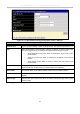
Profile ID
This is the identifier number for this profile set.
Mode
Select Permit to specify that the packets that match the access profile are forwarded by
the Switch, according to any additional rule added (see below).
Select Deny to specify that packets that do not match the access profile are not
forwarded by the Switch and will be filtered.
Access ID
Type in a unique identifier number for this access. This value can be set from 1 - 100.
• Auto Assign – Checking this field will instruct the Switch to automatically
assign an Access ID for the rule being created.
Type
Selected profile based on Ethernet (MAC Address), IP address, or Packet Content
Mask.
• Ethernet instructs the Switch to examine the layer 2 part of each packet
header.
• IP instructs the Switch to examine the IP address in each frame's header.
• Packet Content Mask instructs the Switch to examine the packet header.
Priority
This parameter is specified if you want to re-write the 802.1p default priority previously
set in the Switch, which is used to determine the CoS queue to which packets are
forwarded to. Once this field is specified, packets accepted by the Switch that match this
priority are forwarded to the CoS queue specified previously by the user.
Replace priority with − Click the corresponding box if you want to re-write the 802.1p
default priority of a packet to the value entered in the Priority field, which meets the
criteria specified previously in this command, before forwarding it on to the specified
CoS queue. Otherwise, a packet will have its incoming 802.1p user priority re-written to
its original value before being forwarded by the Switch.
For more information on priority queues, CoS queues and mapping for 802.1p, see the
QoS section of this manual.
Offset
This field will instruct the Switch to mask the packet header beginning with the offset
value specified:
• value (0-15) - Enter a value in hex form to mask the packet from the beginning
of the packet to the 15th byte.
• value (16-31) - Enter a value in hex form to mask the packet from byte 16 to
byte 31.
• value (32-47) - Enter a value in hex form to mask the packet from byte 32 to
byte 47.
• value (48-63) - Enter a value in hex form to mask the packet from byte 48 to
byte 63.
• value (64-79) - Enter a value in hex form to mask the packet from byte 64 to
byte 79.
Port
The Access Rule may be configured on a per-port basis by entering the port number of
the switch in the switch stack into this field. When a range of ports is to be configured,
the Auto Assign check box MUST be clicked in the Access ID field of this window. If
not, the user will be presented with an error message and the access rule will not be
configured. The port list is specified by listing the lowest switch number and the
beginning port number on that switch, separated by a colon. Then the highest switch
number, and the highest port number of the range (also separated by a colon) are
s
p
ecified. The be
g
innin
g
and end of the
p
ort list ran
g
e are se
p
arated b
y
a dash. For