D-Link DES-1526 Web-Smart 26-Port Ethernet Switch with 24 10/100Mbps 802.
FCC Warning This equipment has been tested and found to comply with the limits for a Class A digital device, pursuant to Part 15 of the FCC Rules. These limits are designed to provide reasonable protection against harmful interference when the equipment is operated in a commercial environment. This equipment generates, uses, and can radiate radio frequency energy and, if not installed and used in accordance with this manual, may cause harmful interference to radio communications.
Ceci est un produit de classe A. Dans un environnement domestique, ce produit pourrait causer des interférences radio, auquel cas l`utilisateur devrait prendre les mesures adéquates. Attenzione! Il presente prodotto appartiene alla classe A. Se utilizzato in ambiente domestico il prodotto può causare interferenze radio, nel cui caso è possibile che l`utente debba assumere provvedimenti adeguati.
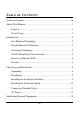
TABLE OF C ONTENTS Table of Contents.........................................................................................iii About This Manual........................................................................................1 Purpose ...................................................................................................1 Terms/Usage ..........................................................................................1 Introduction................................................
Front Panel............................................................................................14 LED Indicator:..............................................................................14 10/100Mbps PoE Ports (Port 1~24):..........................................14 1000BASE-T Gigabit Ethernet Ports (Port 25~26): .................15 mini-GBIC Ports (Port 25F~26F):...............................................15 Reset:..............................................................................
mini-GBIC (Use Combo ports or SFP)......................................19 Configuration ................................................................................................20 Installing the Web Management Utility...........................................20 Discovery List......................................................................................21 Monitor List..........................................................................................22 View Trap .......................
Setup Menu ..........................................................................................31 Configuring Setup Setting..................................................................32 Port Settings ................................................................................32 802.1Q VLAN Settings (Virtual Local Area Network)............34 Trunk Setting...............................................................................37 Mirror Setting ...........................................
A BOUT T HIS M ANUAL Congratulations on your purchase of the DES-1526. This Switch integrates 100Mbps Fast Ethernet and 10Mbps Ethernet network capabilities in a highly flexible package. Since this Switch’s Port-1 to Port-24 are Power over Ethernet (PoE) ports, it will automatically detect the presence of IEEE 802.3afcompliant devices and will provide power through these PoE ports. The Switch provides up to 15.
I NTRODUCTION This chapter describes the features of the DES-1526 and some background information about Fast Ethernet, Gigabit Ethernet, Switching, VLAN, and Power over Ethernet technologies. Fast Ethernet Technology The growing importance of LANs and the increasing complexity of desktop comp uting applications are fueling the need for high performance networks. A number of high-speed LAN technologies have been proposed to provide greater bandwidth and improve client/server response times.
Gigabit Ethernet Technology Gigabit Ethernet is an extension of IEEE 802.3 Ethernet utilizing the same packet structure, format, and support for CSMA/CD protocol, full-duplex, flow control, and management objects, but with a tenfold increase in theoretical throughput over 100Mbps Fast Ethernet and a one hundred-fold increase over 10Mbps Ethernet.
Switching Technology Another approach to pushing beyond the limits of Ethernet technology is the development of switching technology. A switch bridges Ethernet packets at the MAC address level of the Ethernet protocol transmitting among connected Ethernet or Fast Ethernet LAN segments. Switching is a cost-effective way of increasing the total network capacity available to users on a local area network.
VLAN (Virtual Local Area Network) A VLAN is a group of end-stations that are not constrained by their physical location and can communicate as if a common broadcast domain, a LAN. The primary utility of using VLAN is to reduce latency and the need for routers, using faster switching instead. Other VLAN utility includes: u Security: Security is increased with the reduction of opportunity in eavesdropping on a broadcast network because data will be switched to only those confidential users within the VLAN.
Power over Ethernet (PoE) Power over Ethernet (PoE) integrates power and data onto one single cabling infrastructure, eliminating the need to have AC power available at all locations. Power and Data are integrated onto the same cable. Supporting category 5/5e up to 100 Meters, PoE will provide power to PoE compatible devices, such as IP telephones, wireless LAN access points, and IP security cameras.
u Store-and-Forward switching scheme capability to support rate adaptation and ensure data integrity u Up to 4K unicast addresses entities per device, self-learning, and table aging u 768KBytes packet buffer u Supports IEEE 802.3x flow control for full-duplex mode ports u Supports Back-pressure flow control for half-duplex mode ports u Supports 802.
U NPACKING AND I NSTALLATION This chapter provides unpacking and installation information for the Switch. Unpacking Open the shipping cartons of the Switch and carefully unpacks its contents.
u u u Leave at least 10cm (4 in.) of space at the front and rear of the Switch for ventilation. Install the Switch on a sturdy, level surface that can support its weight, or in an EIA standard-size equipment rack. For information on rack installation, see the next section, titled Rack Mounting. When installing the Switch on a level surface, attach the rubber feet to the bottom of each device. The rubber feet cushion the Switch and protect the Switch case from scratching.
Installing the Switch on a Rack The Switch can be mounted in an EIA standard-size, 19-inch rack, which can be placed in a wiring closet with other equipment. Attach the mounting brackets at the Switch’s front panel (one on each side), and secure them with the provided screws. Figure 2. Combine the Switch with the provided screws . Then, use screws provided with the equipment rack to mount each switch in the rack.
Figure 3. Mount the Switch in the rack . Connecting Network Cables The Switch supports 24 10/100BASE-TX Fast Ethernet PoE enabled ports and 2 1000BASE-T/mini-GBIC combo ports. These 24 PoE ports will be automatically activated when a compatible terminal is identified. The Switch will supply power through the PoE port to the connected PD. For Legacy devices that are not yet compatible, the PoE port will not offer the power to these devices.
be turned on without having any or all LAN segment cables connected.
I DENTIFYING E XTERNAL C OMPONENTS This chapter describes the front panel, rear panel, and LED indicators of the Switch. Front Panel The figure below shows the front panels of the Switch. Figure 5. Front panel view LED Indicator: Comprehensive LED indicators display the status of the Switch and the network (see the LED Indicators chapter below). 10/100Mbps PoE Ports (Port 1~24): These ports are PoE enable ports.
For legacy devices that are not yet compatible, the PoE port will not offer the power to these devices. This feature allows users to freely and safely mix legacy and Power over Ethernet compatible devices on their network. These ports support network speeds of either 10Mbps or 100Mbps, and can operate in half- and full-duplex transfer modes. These ports also support the automatic MDI/MDIX crossover detection function, providing true “plug and play” capability.
Reset: The Reset button is to reset all settings back to the factory defaults. Note: Be sure that you record the settings of your device, or else all settings will be erased when pressing the “Reset” button. Rear Panel Figure 6. Rear panel of the Switch AC Power Connector: This is a three-pronged connector that supports the power cord. Plug in the female connector of the provided power cord into this connector, and the male into a power outlet. Supported input voltages range from 100-240V AC at 50-60Hz.
U NDERSTANDING LED INDICATORS The front panel LEDs provide instant status feedback, and helps monitor and troubleshoot when needed. Figure 7. LED indicators of the Switch System LEDs POWER: On : When the Power LED lights on, the Switch is receiving power. Off : When the Power turns off or the power cord has improper connection. Power Maximum (PWR MAX) On : When the system power resource remain <=15.
CPU: Management Indicator Blinking : When the CPU is working, the CPU LED is blinking. On/Off : The CPU is not working. Fast Ethernet PoE Port Status LEDs (Port 1 ~ 24) Link/ACT: Link/Activity : When the Link/ACT LED lights on, the respective port is successfully connected to an Ethernet network. Blinking : When the Link/ACT LED is blinking, the port is transmitting or receiving data on the Ethernet network. On Off : There is no link.
output port. Gigabit Ethernet Port Status LEDs Link/ACT: Link/Activity : When the Link/ACT LED lights on, the respective port is successfully connected to an Ethernet network. Blinking : When the Link/ACT LED is blinking, the port is transmitting or receiving data on the Ethernet network. On Off : There is no link. 1000Mbps On : When the 1000Mbps LED lights on, the respective port is connected to a 1000Mbps Gigabit Ethernet network.
C ONFIGURATION Through the Web browser you can configure Switch functions such as VLAN, Trunking, and QoS… etc. With the attached Web Management Utility, you can easily discover all the Web Management Switches, assign the IP Address, changing the password , and upgrade new firmware. Installing the Web Management Utility The following instructions guide you through the installation of the Web Management utility. 1. Insert the Utility CD in the CD-ROM Drive. 2.
Figure 8. Web Management Utility The Web Management Utility is divided into four parts, Discovery List, Monitor List, Device Setting, and Toolbar function, for detailed instructions, follow the section below. Discovery List This is the list where you can discover all the Web management devices in the entire network. By pressing the “Discovery” button, you can list all the Web Management devices in the discovery list.
System word definitions in the Discovery List: u MAC Address: Shows the device MAC Address. u IP Address: Shows the current IP address of the device. u Protocol version: Shows the version of the Utility protocol. u Product Name: Shows the device product name. u System Name: Shows the appointed device system name. u Location: Shows where the device is located. u Trap IP: Shows the IP where the Trap is to be sent. u Subnet Mask: Shows the Subnet Mask set of the device.
u Gateway: Shows the Gateway set of the device. View Trap The Trap function can receive the events that happen on the Web Management Switch in the Monitor List. There is a light indicator behind the “View Trap” button. When the light is green, it means that there is no trap transmitted, and when it is red, it means that a new trap has been transmitted, reminding us to view the trap. (Figure 9) Figure 9. View trap button When the “View Trap” button is clicked, a Trap Information window will pop up.
Note: In order to receive Trap information, the Switch has to be configured with Trap IP and Trap Events in the Web browser. These settings are available in the Trap Setting Menu. Add Item To add a device to the Monitor List manually, enter the IP Address of the device that you want to monitor. Delete Item To delete the device in the Monitor List. Device Setting You can set the device by using the function key in the Device Setting Dialog box.
must fill in the password and press the “Set” button to process the data change immediately. Figure 11. Configuration Setting Password Change You can use this when you need to change the password . Fill in the required passwords in the dialog boxes and press the “Set” button to process the password change immediately. Figure 12.
Firmware Upgrade When the device has a new function, there will be a new firmware to update the device; use this function to upgrade the firmware. Figure 13. Firmware upgrade Web Access Double click the device in the Monitor List or select a device in the Monitor List and press the “Web Access” button to access the device in a Web browser.
Toolbar The toolbar in the Web Management Utility has four main tabs: File, View, Options, and Help. File TAB In the “File TAB”, there is Monitor Save, Monitor Save As, Monitor Load, and Exit. Monitor Save: To record the settings of the Monitor List to the default settings so that when you open the Web Management Utility the next time, it will automatically load the default recorded setting. Monitor Save As: To record the setting of the Monitor List to an appointed filename and file path.
Option TAB In the “Option TAB”, there is the Refresh Time function. This function helps you to refresh the time for monitoring the device. Choose 15 secs, 30 secs, 1 min, 2 min, and 5 min to select the time for monitoring. Help TAB In the “Help TAB”, there is the About function; it displays the version of the Web Management Utility. Configuring the Switch The DES-1526 has a Web GUI interface for smart switch configuration. The Switch can be configured through the Web browser.
Login Before you configure this device, note that when the Web Smart Switch is configured through an Ethernet connection, make sure the manager PC must be set on same the IP network. For example, when the default IP address of the Web Smart Switch is 192.168.0.1, then the manager PC should be set at 192.168.0.x (where x is a number between 2 and 254), and the default subnet mask is 255.255.255.0. Open the Web browser program and Enter IP address http://192.168.0.
Figure 15 After entering the password, the main page appears, and the screen will display the device status.
Setup Menu When the main page appears, the Setup menu is on the left side of the screen (Figure 17). Click on the setup item that you want to configure. There are eleven options: Port Settings, VLAN Settings, Trunk Settings, Mirror Settings, SNMP Settings, PoE Settings, Device Status, Statistics, System Settings, Trap Settings, Password Settings, Backup Settings, and Reset Settings as shown in the Main Menu screen.
Figure 17. Setup menu Configuring Setup Setting There are six items , including Port Settings, VLAN Settings, Trunk Settings, Mirror Settings, SNMP Settings, and PoE Settings in Setup menu. Port Settings In the Port Settings menu (Figure 18), this page will display each port’s status. Press the ID parameter to set each port’s Speed, Flow Control, QoS and Link Status. When you need to renew the posted information, press the “Refresh” button.
Figure 18. Port Configuration To change the port setting, click on the ID parameter to enter the selected port to configure its Speed/Disable and Flow control. Figure 19. Port Settings.
Speed/Disable: This setting has six modes— 100M Full, 100M Half, 10M Full, 10M Half, Auto, and Disable— for speed or port disable selections. Flow Control: This setting determines whether or not the Switch will be handling flow control. Set FlowCtrl to Enable for avoiding data transfer overflow. If it is set to Disable, there is either no flow control or other hardware/software management.
VID: Select the VID group that you set. When you select VID Table Setting, press “Add new VID” to create new VID group, from port 01 ~ port 26 (26F), select Untag Port, Tag Port, or Not Member for each port. To save the VID group, press the “Apply” button. To remove the selected VID group, select the VID group and press “Remove the VID” button. To modify the VID group setting, select the VID group and change the setting, and press the “Apply” button to save the settings. Figure 20.
When you select Port VLAN setting, fill in each port’s PVID value between 1 and 4094. Figure 21.
Trunk Setting The Trunk function enables you to cascade two or more devices with larger bandwidths. There are four Trunking groups to be set; and there are default ports in each member. Checked “Enable” to use the trunk function, select the ports in each member to be trunk, and click “Apply” to activate the selected trunk group. Figure 22. Trunk Settings Be sure that the selected trunk setting port is connected to the device with a same VLAN group.
Mirror Setting Port Mirroring is a method of monitoring network traffic that forwards a copy of each incoming and/or outgoing packet from one port of a network switch to another port where the packet can be studied. It enables the manager to keep close track of switch performance and alter it if necessary. Configuring the port mirroring by assigning a source port from which to copy all packets and a sniffer port where those packets will be sent.
Figure 23. Mirror Setting. SNMP Setting Simple Network Management Protocol (SNMP) is an OSI Layer 7 (Application Layer) designed specifically for managing and monitoring network devices. SNMP enables network management stations to read and modify the settings of gateways, routers, switches, and other network devices. Use SNMP to configure system features for proper operation, mo nitor performance and detect potential problems in the Switch, switch group, or network.
private - Allows authorized management stations to retrieve and modify MIB objects. Traps Traps are messages that alert network personnel of events that occur on the Switch. The events can be as serious as a reboot (someone accidentally turned OFF the Switch), or less serious like a port status change. The Switch generates traps and sends them to the trap recipient (or network manager).
Configure SNMP Community: Figure 24. SNMP Community Setting Add Group: To add a SNMP Community group, press the “Add Group” button. The Add SNMP Community configuration window will pop up. Fill in the community name and assign the community enable read_only or read_write. Press the “Apply” button to execute the setting. Figure 25.
Delete Group: To delete previously defined SNMP Community group, press the “Delete Group” button. The Delete SNMP Community configuration window will pop up; check the delete dialog box. Press “Apply” to delete the selected SNMP Community Group. Figure 26. Delete SNMP Community group Modify Group: To modify a previously defined SNMP Community group, click on the ID parameter to enter to the selected SNMP Community Group to configure its community name and community enable.
Configure SNMP Trap: Figure 28. Configure SNMP Trap Setting Trap authentication fail: When checked, the dialog box of the Trap authentication fail. A trap when authentication fails, the Switch will trap the authentication failure even to the SNMP host. Power on/power off & threshold above/below: When checked the dialog box of the power on/power off & power threshold above/below.
Figure 29. Add SNMP Trap System Events: Monitoring the Switch status. Device bootup: A trap when the Switch Bootup was successful. Fiber Port Events: Monitoring the Fiber port status. Link Up/Link Down: A trap when there is linking status in the fiber port. Abnormal* Receive Error: A trap when there is a receive data error in the fiber port. Abnormal* Transmit Error: Atrap when there is a transmit data error in the fiber port. Twisted Pair Port Events: Monitoring the twisted pair port status.
Abnormal*: 50 error packet count within 10 seconds. PoE Events: Monitoring the PoE ports status. PoE Power fail: A trap when the port’s power source fails or the PD64012 fails. Power over current: A trap when the PoE port’s power is over current. Power short circuit: A trap when the PoE port’s power circuit was short. Delete Trap: To delete previously defined SNMP Trap, press the “Delete Trap” button. The Delete SNMP Trap Delete configuration window will pop up; check the delete dialog box.
Figure 31.
PoE Setting When you click on the PoE Setting, the PoE Status will appear on the screen. It will display the PoE status including, Port Enable, Power limit, Power (W), Voltage(V), Current (mA), Classification, Port status, System Budget Power, Support Total Power, Remainder Power, and The ratio of system power supply. Note: The PoE Status information of Power current, Power Voltage, and Current is the power usage information of the connected PD; please “Refresh” to renew the information.
Figure 32. PoE Status POE Port Status: Selected “POE Port Status” to configure the PoE Port setting. To configure the settings, click on the ID parameter to enter the selected port. Figure 33. PoE Port Setting Poe Enable: Select to enable or disable the PoE function. Power limit: This function allows you to manually set the port power current limitation to be given to the PD.
Figure 34.
System power Threshold: When the radio of the system power supply is large than or smaller than the System power Threshold setting, the Switch will send trap event to the Management Station. Note: When there is a system power shortage with the PD, the Switch will enforce the PoE port priority management. The lower port number will have the higher priority than the higher port number, Port 1 > Port 2 > … > Port 24. Device Status Click on the “Status” button to display the device status on this screen.
Figure 35.
Statistics The Statistics Menu screen will display the status of each port packet count. Figure 36. Statistic For detailed packet information, click on the ID parameter as Figure 26.
Figure 37. Port Statistics System Setting The System Setting includes the System name, Location name, Login Timeout, IP Address, Subnet Mask, and Gateway. Through the Web Management Utility, you can easily recognize the device by using the System Name and the Location Name. The Login Timeout is to set the idle time-out for security issues, When there is no action when running the Web Smart Utility and the time is up, you must re-login to Web Smart Utility before you set the Utility.
54
Trap Setting The Trap Setting enables the device to monitor the Trap through the Web Management Utility. Set the Trap IP Address of the manager where the trap is to be sent. Figure 39. Trap Setting System Events: Monitoring the system’s trap. Device Bootup: A trap when booting up the system. Illegal Login: A trap when there is an incorrect password login. It will record the IP that attempted to login.
Fiber Port Events: Monitoring the Fiber port status. Link Up/Link Down: A trap when there is linking status in the fiber port. Abnormal* Receive Error: A trap when there is a receive data error in the fiber port. Abnormal* Transmit Error: A trap when there is a transmit data error in the fiber port. Twisted Pair Port Events: Monitoring the twisted pair port status. Abnormal* Receive Error: A trap when there is a receive data error in the twisted pair port.
Set Password Password is the invaluable tool for the manager to secure the Web Management Switch. You can use this function to change the password. If you forget the password, press the “Reset” button in the rear panel of the Switch. The current setting includes VLAN, Port Setting… etc. will be lost and the Switch will be restored to the default setting. Figure 40.
Backup Setting The backup tools help you to backup the current setting of the Switch. Once you need to backup the setting, press the “Backup” button to save the setting. To restore a current setting file to the device, you must specify the backup file and press the “Restore” button to process the setting of the recorded file. Figure 41. Backup Setting Note: When restoring a recorded file, the current password will not be erased.
Reset Setting The Factory Reset button helps you to reset the device back to the default setting from the factory. Be aware that the entire configuration will be reset, the IP address of the device will be retrieved from DHCP server (factory default is DHCP enabled) or the default IP address of 192.168.0.1 will be used when the device fails to retrieve the IP address from DHCP server. Figure 42.
T ECHNICAL S PECIFICATIONS General Standards IEEE 802.3 10BASE-T Ethernet IEEE 802.3u 100BASE-TX Fast Ethernet IEEE 802.3ab 1000BASE-T Gigabit Ethernet IEEE 802.3x Full Duplex Flow Control IEEE 802.3af compliant Protocol CSMA/CD Data Transfer Rate Ethernet: 10Mbps (half-duplex), 20Mbps (fullduplex) Fast Ethernet: 100Mbps (half-duplex), 200Mbps (full-duplex) Gigabit Ethernet: 2000Mbps (full-duplex) Topology Star Network Cables 10BASET: 2-pair UTP Cat. 3, 4, 5; up to 100m 100BASE-TX: 2-pair UTP Cat.
Power over Ethernet Standard IEEE 802.3af Power current Up to 15.4W per port Maximum 170W per device PD Classification Auto PD classification identify PoE pin assignment Power(+): pin 3 & pin 6 in RJ-45 Power(-): pin 1 & pin 2 in RJ-45 Safety protection Over current protect Circuit shortage protect Physical and Environmental AC inputs 100-240V AC, 50-60 Hz internal universal power supply Power Consumption 9Watts (max. no PD Device connected) 180Watts (max. with 11 x 15.
Performance Transmits Method: Store-and-forward Filtering Address Table: 4K entries per device Packet Filtering/Forwar ding Rate: 10Mbps Ethernet: 14,880/pps 100Mbps Fast Ethernet: 148,800/pps 1000Mbps Gigabit Ethernet: 1,488,000/pps MAC Address Learning: Automatic update Transmits Method: Store-and-forward RAM Buffer: 768K bytes per device 60
Warranty and Registration Information (All countries and regions excluding USA and Europe) Wichtige Sicherheitshinweise 1. Bitte lesen Sie sich diese Hinweise sorgfältig durch. 2. Heben Sie diese Anleitung für den spätern Gebrauch auf. 3. Vor jedem Reinigen ist das Gerät vom Stromnetz zu trennen. Vervenden Sie keine Flüssig- oder Aerosolreiniger. Am besten dient ein angefeuchtetes Tuch zur Reinigung. 4.
e. Das Gerät ist gefallen und/oder das Gehäuse ist beschädigt. f. Wenn das Gerät deutliche Anzeichen eines Defektes aufweist. 16. Bei Reparaturen dürfen nur Orginalersatzteile bzw. den Orginalteilen entsprechende Teile verwendet werden. Der Einsatz vo n ungeeigneten Ersatzteilen kann eine weitere Beschädigung hervorrufen. 17. Wenden Sie sich mit allen Fragen die Service und Repartur betreffen an Ihren Servicepartner. Somit stellen Sie die Betriebssicherheit des Gerätes sicher. 18.
If the product proves defective within the applicable warranty period, D -Link will provide repair or replacement of the product. D -Link shall have the sole discretion whether to repair or replace, and replacement product may be new or reconditioned. Replacement product shall be of equivalent or better specifications, relative to the defective product, but need not be ide ntical.
Subject to the terms and conditions set forth herein, D-Link Systems, Inc. (“D -Link”) provides this Limited Warranty: • Only to the person or entity that originally purchased the product from D-Link or its authorized reseller or distributor, and • Only for products purchased and delivered within the fifty states of the United States, the District of Columbia, U.S. Possessions or Protectorates, U.S. Military Installations, or addresses with an APO or FPO.
functional specifications for the Software or to refund the portion of the actual purchase price paid that is attributable to the Software. Except as otherwise agreed by D-Link in writing, the replacement Software is provided only to the original licensee, and is subject to the terms and conditions of the license granted by D-Link for the Software. Replacement Software will be warranted for the remainder of the original Warranty Period and is subject to the same limitations and exclusions.
an address in the United States, otherwise we will ship the product to you freight collect. Expedited shipping is available upon request and provided shipping charges are prepaid by the customer. D-Link may reject or return any product that is not packaged and shipped in strict compliance with the foregoing requirements, or for which an RMA number is not visible from the outside of the package.
WARRANTIES AND REMEDIES ARE EXCLUSIVE AND ARE IN LIEU OF ANY OTHER WARRANTIES OR REMEDIES, EXPRESS, IMPLIED OR STATUTORY. Governing Law: This Limited Warranty shall be governed by the laws of the State of California. Some states do not allow exclusion or limitation of incidental or consequential damages, or limitations on how long an implied warranty lasts, so the foregoing limitations and exclusions may not apply.
Product Registration Register online your D-Link product at http://support.dlink.com/register/ Product registration is entirely voluntary and failure to complete or return this form will not diminish your warranty rights.
- Trademarks Copyright 2002 D-Link Corporation. Contents subject to change without prior notice. D-Link is a registered trademark of D-Link Corporation/ D-Link Systems Inc. All other trademarks belong to their respective proprietors.
Geographical Scope of the Limited Product Warranty This Limited Product Warranty is applicable in all European Countries as listed in the addendum “European Countries for D-LINK Limited Product Warranty”. The term “European Countries” in this D-LINK Limited Product Warranty only include the countries as listed in this addendum.
This Limited Product Warranty extends only to the original end-user purchaser of this D-LINK Hardware Product and is not transferable to anyone who obtains ownership of the D-LINK Hardware Product from the original end-user purchaser. Product Type Product Warranty Period Managed Switches (i.e. switches with built in SNMP agent)(including modules and management software) Five (5) years All other products Two (2) years Spare parts (i.e.
Telephone: +44-020-8731-5555 Facsimile: +44-020-8731-5511 www.dlink.co.
D-Link Europe Limited Produktgarantie Allgemeine Bedingungen Die hierin beschriebene eingeschränkte Garantie wird durch D-LINK (Europe) Ltd. gewährt (im Folgenden: „DLINK“). Diese eingeschränkte Garantie setzt voraus, dass der Kauf des Produkts nachgewiesen wird. Auf Verlangen von D-LINK muss auch dieser Garantieschein vorgelegt werden. AUSSER IN DEM HIER AUSDRÜCKLICH BESCHRIEBENEN UMFANG GEWÄHRT D-LINK KEINE WEITEREN GARANTIEN, WEDER AUSDRÜCKLICH NOCH STILLSCHWEIGEND.
D-LINK gewährleistet, dass die nachstehend aufgeführten Produkte bei gewöhnlicher Verwendung für die unten angegebene Laufzeit der eingeschränkten Garantie („Garantielaufzeit“) frei von wesentlichen Verarbeitungs- und Materialfehlern sind. Voraussetzung hierfür ist jedoch, dass das Produkt entsprechend dem Benutzerhandbuch und den weiteren Dokumentationen, die der Benutzer beim Kauf (oder später) erhalten hat, genutzt und gewartet wird.
Die oben aufgeführten Garantielaufzeiten gelten für alle D-LINK-Produkte, die in europäischen Staaten ab dem 1. Januar 2004 von D-LINK oder einem autorisierten Fachhändler oder Distributor verkauft werden. Alle vor dem 1. Januar 2004 von D-LINK oder einem autorisierten Vertragshändler oder Distributor verkauften Produkte haben eine Gewährleistung von 5 Jahren; ausgenommen sind Netzteile, Lüfter und Zubehör, diese haben eine Garantie von 2 Jahren.
D-Link Europe a limité la garantie des produits Conditions Générales La Garantie Produit Limitée énoncée ci-dessous émane de D-LINK (Europe) Ltd. (ci-après « D-LINK »). Cette Garantie Produit Limitée n’est valable que sur présentation de la preuve d’achat. D-LINK peut également exiger la présentation du présent bon de garantie.
qu’ils soient utilisés et entretenus conformément au manuel utilisateur et aux autres documents remis au client lors de l’achat (ou amendés de temps à autre). D-LINK ne garantit pas le fonctionnement ininterrompu ou sans erreur de ses produits. D-LINK ne s’engage pas non plus à corriger tous les défauts, erreurs ou non conformités.
La période de garantie indiquée sur ce bon annule et remplace celle qui figure dans le manuel utilisateur ou dans le contrat d’achat des produits considérés. Pour éviter le doute, si vous avez acheté votre produit D-LINK en tant que consommateur, vos droits légaux demeurent inchangés.
Garantía limitada del producto D-LINK Europa Condiciones generales Esta garantía la ofrece D-LINK (Europe) Ltd. (en este documento, "D-LINK"). La garantía limitada del producto sólo es válida si se acompaña del comprobante de la compra. También deberá presentarse la tarjeta de garantía si DLINK lo solicita.
D-LINK garantiza que los productos descritos más adelante están libres de defectos de fabricación y materiales, en condiciones normales de uso, a lo largo del período de la garantía limitada del producto que se indica en este documento ("período de la garantía limitada del producto"), si el producto se ha utilizado y mantenido conforme a lo recogido en el manual del usuario o en otra documentación que se haya proporcionado al comprador en el momento de la compra (o que se haya corregido).
Todos los productos comprados en países europeos a D-LINK o a uno de sus proveedores o distribuidores autorizados antes del 1 de enero del 2004 cuentan con 5 años de garantía, excepto las fuentes de alimentación, los ventiladores y los accesorios, que cuentan con 2 años de garantía. El período de garantía que figura en esta tarjeta sustituye y reemplaza al período de garantía que consta en el manual del usuario o en el contrato de compra de los productos correspondientes.
D-Link Europe Termini di Garanzia dei Prodotti Generalità La presente Garanzia viene fornita da D-LINK (Europe) Ltd. (di seguito denominata "D-LINK"). Essa viene riconosciuta solo se accompagnata dalla prova di acquisto. D-LINK può richiedere anche l’esibizione della presente cartolina di garanzia.
funzionamento del prodotto sarà ininterrotto o esente da errori né tanto meno che tutti gli eventuali errori, carenze, difetti o non conformità potranno essere corretti.
Il periodo di garanzia qui menzionato sostituisce qualsiasi altro periodo di garanzia definito nel manuale d’uso o nel contratto di acquisto del prodotto. Se avete acquistato un prodotto D-LINK in qualità di consumatore i Vostri diritti rimangono invariati.