D-Link DVG-1402S 2Voice + 4SW VoIP Router Manual Building Networks for People Version B.
Contents Package Contents........................................................................................................... 3 Introduction ..................................................................................................................... 4 Rear Panel Connections................................................................................................. 5 Front Panel LEDs .........................................................................................................
Home > VoIP > Manage Features > Reject Incoming Call........................................ 31 Home > VoIP > Manage Features > Block Outgoing Call ......................................... 32 Home > DHCP ........................................................................................................... 33 Home > Proxy DNS ................................................................................................... 35 Advanced > Virtual Server ..................................................
Package Contents • • • • • D-Link DVG-1402S Router Power Adapter - AC 12V, 1.2A Manual and Warranty on CD Quick Installation Guide Ethernet Cable (All the Ethernet ports on DVG-1402S are Auto-MDIX) Note: Using a power supply with a different voltage rating than the one included with the DVG-1402S will cause damage and void the warranty for this product. If any of the above items are missing, please contact your reseller.
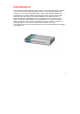
Introduction The D-Link DVG-1402S High-Speed VoIP Router Links traditional telephony networks to IP networks with conventional telephony devices such as analog phones or fax machines. It can reduce long distance phone charges and deliver toll-quality voice communication over the IP network. This gateway provides two loop start Foreign Exchange Subscriber (FXS) ports and four LAN ports.
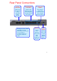
Rear Panel Connections Phone Connections Auto MDI/MDIX LAN Ports Factory Reset Button Connect to your phones using standard phone cabling. Connect the Ethernet cable from computers on your LAN to these ports. Pressing this button will restore the router to its factory default settings. All Ethernet Ports (WAN and LAN) are auto MDI/MDIX, meaning you can use either a straight-through or a crossover Ethernet cable. WAN Port Connect the Ethernet cable from your ADSL modem to this port.
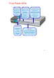
Front Panel LEDs Status LED WAN LED Phone LEDs A blinking LED indicates the DVG-1402S is functioning properly. An active LED indicates a link has been established. A blinking LED indicates activity on the WAN port. The Hook LED will light when a telephone is off the hook. A blinking LED indicates an incoming call is detected. Power LED A solid light indicates a valid connection to the power supply. LAN LEDs An active LED indicates a link has been established.
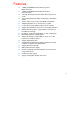
Features • • • • • • • • • • • • • • • • • • • 1 NWay 10/100BASE-TX Fast Ethernet port for WAN-connection 4 NWay 10/100BASE-TX Fast Ethernet port for LAN-connection 2 Foreign Exchange Subscriber (FXS) POTS ports (RJ-11 Jacks) Voice Activity Detection (VAD) /Comfort Noise Generation (CNG) Silence suppression to reduce bandwidth consumption. Adaptive jitter buffer for a smooth voice reception Lost packet recovery ability for improved voice quality Support QoS (Quality of Service) for voice quality guarantee.
Installation For a typical setup at home, please do the following: 1. You will need broadband Internet access (a Cable or DSL-subscriber line into your home or office) 2. Consult with your Cable or DSL provider for proper installation of the modem 3. Connect the Cable or DSL modem to the DVG-1402S VoIP Router (see the printed Quick Installation Guide included with your router.) 4. Install the D-Link DFE-530TX+ adapter into a desktop computer.
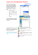
Using the Configuration Wizard Whenever you want to configure your network or the DVG-1402S, you can access the Configuration Menu by opening the web-browser and typing in the IP Address of the DVG-1402S. The DVG-1402S default IP Address is shown to the right: • Open the web browser • Type in the IP Address of the Router (http://192.168.15.1) • Type admin in the User Name field • Type admin in the Password field • Click OK 192.168.15.1 The Home > Wizard screen will appear.
Home > WAN Dynamic Choose Dynamic IP Address to obtain IP Address information automatically from your ISP. This option should be selected if your ISP has not supplied you with an IP address. This option is commonly used for Cable modem services. Host Name The Host Name is optional but may be required by some ISPs. The default host name is the device name of the Router and may be changed. MAC Address The default MAC Address is set to the WAN’s physical interface MAC address on the Broadband Router.
MAC address on the Broadband Router. You can use the “Clone MAC Address” button to copy the MAC address of the Ethernet Card installed by your ISP and replace the WAN MAC address with the MAC address of the router. It is not recommended that you change the default MAC address unless required by your ISP. Upstream Bandwidth Enter a DNS Address if you wish not to use the address provided by your ISP. The upstream bandwidth can be set for the data traffic.
Home > WAN > Static IP Address Static IP Address Choose Static IP Address if all WAN IP information is provided to you by your ISP. You will need to enter in the IP address, subnet mask, gateway address, and DNS address(es) provided to you by your ISP. Each IP address entered in the fields must be in the appropriate IP form, which are four octets separated by a dot (x.x.x.x). The Router will not accept the IP address if it is not in this format.
Secondary DNS Address Upstream Bandwidth Input the primary DNS (Domain Name Server) IP address provided by your ISP This is an optional DNS Address entry to be used if the primary DNS Fails. The upstream bandwidth can be set for the type of packets that the will be sent. The bandwidth can be maximized for voice packets and limited for data that requires less throughput.
Home > WAN > PPPoE Choose PPPoE (Point to Point Protocol over Ethernet) if your ISP uses a PPPoE connection. Your ISP will provide you with a username and password. This option is typically used for DSL services. PPPoE Choose this option if your ISP uses PPPoE. (Most DSL users will select this option.) Password Retype Password Service Name IP Address Enter The PPPoE user name provided to you by your ISP. Retype the password entered in the previous field.
provided by your ISP Secondary DNS Address Upstream Bandwidth This is an optional DNS Address entry to be used if the primary DNS fails. The upstream bandwidth can be set to suit the type of packets that the connection will be sending. The bandwidth can be maximized for voice packets and limited for data that requires less throughput.
Home > LAN LAN is short for Local Area Network. This is considered your internal network. These are the IP settings of the LAN interface for the DVG-1402S and may be referred to as Private settings. You may change the LAN IP address if needed. The LAN IP address is private to your internal network and cannot be seen on the Internet. IP Address Subnet Mask The IP address of the LAN interface. The default IP address is 192.168.15.1. The subnet mask of the LAN interface. The default subnet mask is 255.255.
Home > VoIP All of the screens necessary to setup and configure the router to handle VoIP traffic are accessed from the screen shown below. To access any of the individual configuration screens, click on the corresponding radio-button and that screen will appear.
Home > VoIP > Server Configuration The Router can be configured to handle voice signals over the Internet Protocol (Voice over IP − VoIP). The screen shown to the right, along with those on the following pages are used to configure your router to communicate with the devices that will send and receive telephone calls over the Internet.
Server FQDN Use this drop-down menu to Enable or Disable the Server Fully Qualified Domain Name (FQDN) function. This is disabled when the SIP URL domain name is different from the SIP proxy server domain name. The phone will then use the domain name in Domain Name field as part of SIP URL but send and receive SIP messages through the SIP proxy server defined in the Service Domain field. IP Address Enter the IP address of the SIP Server in this field.
Home > VoIP > Provisioning Provisioning is a function that automatically updates your DVG-1402S’s VoIP configuration by using a TFTP server located on the Internet. If you have accesses to such a service, you will need to know the URL and Proxy Address of the Provisioning Server. Provisioning Function Use this drop-down menu to Enable or Disable the Provisioning Function on the router. Server URL Enter the URL of the Provisioning Server in this field.
21
Home > VoIP > STUN Configuration Simple Traversal of UDP over NAT (STUN) − is a protocol which enables a VoIP device, such as this router or an IP phone, to detect the presence and type of NAT behind which the phone is placed. This router supports STUN and can intelligently modify the private IP address and port in its SIP/SDP message by using the NAT mapped public IP address and port through a series of STUN queries against a STUN server located on the public Internet.
Home > VoIP > User Agent The Router can be configured to handle voice signals over the Internet Protocol (Voice Over IP − VOIP). Same Phone Number Use this field to Enable or Disable the use of the same telephone number for the User Agent as for the Server Agent. Index Use this field to assign line 1 or line 2 telephone sockets (on the back of the router) to the information entered in the User Agent. Phone Number The telephone number assigned to the User Agent.
Home > VoIP > Peer to Peer The Router can be configured to handle voice signals over the Internet Protocol (Voice Over IP − VOIP). Phone Number The telephone number assigned to this entry. User IP Address Enter the IP address of the remote peer in this field. Port Enter the UDP port number the remote peer will use to make the connection in this field. If you do not have any information as to the proper port number, leave the default setting here.
Home > VoIP > Telephony The Router can be configured to handle voice signals over the Internet Protocol (Voice Over IP − VoIP). Index Use this field to assign line 1 or line 2 telephone sockets (on the back of the router) to the information entered in the User Agent. DTMF Method Out-of band Dual Tone Multi-frequency -The Dual Tone Multi-frequency (DTMF) mode sets how the router will handle the tones that your telephone makes when you push its buttons.
Home > VoIP > Speed Dial The Router can be configured to dial a specified telephone number when you enter a numerical dial code. For example, you could assign 22 to the telephone number 555-1234. Then you can dial that telephone number by entering 22. Index A number used to identify the current speed dial table entry. Dial Code A numerical code that will correspond to the phone number entered in the field below. You will dial this number, and the router will dial the corresponding telephone number.
Home > VoIP > Misc. Instead of adding additional lines to handle different telephone numbers, distinctive rings can be set to allow more than one telephone number to reach the same line. Calls coming in on different numbers on the same line can be identified by their distinctive ring pattern. For example, you could set a “short-short” ring for the sales department number, and a regular ring for the technical support number. Use the radio button to select Ring Cadence, Ring Default Rule, or Ring Rule.
Home > VoIP > Misc. > Ring Cadence By using the Ring Cadence window, you can set up to 8 distinct ring patterns. The ring pattern of each distinct ring can be configured by setting the On and Off time. The amount of times that the ring pattern will repeat itself can also be set. Duration This field is used to limit the amount of times that the ring pattern will repeat itself.
Home > VoIP > Misc. > Ring Default Rule The Ring Default Rule is set for inbound callers that are not defined by the Ring Rule. One Ring Default Rule can be set for each VoIP port. Ring Cadence Profile ID Use this pull-down menu to select a Ring Cadence for the Ring Default Rule. The 8 different Ring Cadences can be configured on the Ring Cadence window.
Home > VoIP > Misc. > Ring Rule You can use the Ring Rule window to assign Caller IDs to frequently received inbound calls. Any call that has been assigned a caller ID will have its ID number displayed on the receiver’s caller display. This way, the receiver knows which department the inbound call is attempting to reach by the ring cadence, and who the caller is by the caller ID. From Port Ring Cadence Profile ID Caller ID Use the From field to select either VoIP or PSTN.
Home > VoIP > Manage Features > Reject Incoming Call You can configure the router to reject incoming calls from particular telephone numbers by entering the telephone number in the screen shown below. Name PhoneNum Enter a name to identify the current entry. Enter the telephone number you want to block incoming calls from.
Home > VoIP > Manage Features > Block Outgoing Call You can configure the router to reject outgoing calls from particular telephone numbers by entering the telephone number in the screen shown below. Name PhoneNum Enter a name to identify the current entry. Enter the telephone number you want to block outgoing calls to.
Home > DHCP Dynamic Host Configuration Protocol (DHCP) allows the gateway to automatically obtain the IP address from a DHCP server on the service provider’s network. The service provider assigns a global IP address from a pool of addresses available to the service provider. Typically the IP address assigned has a long lease time, so it will likely be the same address each time the Router requests an IP address.
as HTTP or FTP. First, the user must enable the Static DHCP function by clicking the corresponding Enabled radio button. Next the user must enter the host name and the IP address for that computer by entering the last numbers into the space provided in the IP Address field. Next, the user is to enter the MAC address of the computer into the space provided. Click Apply to implement these static settings.
Home > Proxy DNS State Use this drop down menu to enable or disable the Proxy DNS. Proxy DNS IP Address Enter the IP Address of the Proxy DNS.
Advanced > Virtual Server To view the following window, click on the Advanced tab at the top of the window and then click the Virtual Server button to the left. The Virtual Server will allow remote users access to various services outside of their LAN through a public IP address, such as FTP (File Transfer Protocol) or HTTPS (Secure Web). After configuring the Router for these features, the Router will redirect these external services to an appropriate server on the user’s LAN.
These external services may be modified by clicking its corresponding edit icon, or they may be deleted by clicking the corresponding delete icon. Though there are seven fields available to configure the Virtual Server, in most cases, only the IP address of the Virtual Server will be needed for implementation. To enable an already existing Virtual Server, click its corresponding edit button, configure the appropriate fields listed below and set the Status fields to Enabled by clicking the radio button.
Advanced > Filters Packet filtering is a basic security measure that should be used on any network that is exposed to a security risk. A packet filter system examines data packets and scrutinizes them in order to control network access.
passed through the Router from either side of the gateway. The rules are created and controlled by the network administrator and can be precisely defined. These rules are used to block access to the LAN from outside the network and/or to deny access to the WAN from within the network. The Router uses filtering rules to examine data packet headers for specific information. Packets passing through the Router that do not meet the criteria specified by the rule set are dropped.
Protocol The protocol associated with this IP filter. The user may choose between TCP, UDP or Both. IP Address An IP address or range of IP addresses that will be denied access to the Internet. Subnet Mask The subnet mask that corresponds to the IP address above. Start Port/End Port A port or range of ports that will be denied access to the Internet. If no port is entered, all ports in this IP range will be denied access to the Internet.
Advanced > Firewall This Router comes equipped with a firewall. The Firewall configuration screen allows the Router to enforce specific predefined policies intended to protect against certain common types of attacks. To configure the Router’s firewall, click the Advanced tab at the top of the screen and then the Firewall tab to the left. Pass or Block Select the action you want the filter to take when it finds a packet that meets the criteria entered below.
Advanced > Routing > RIP Configuration RIP − Routing Information Protocol − specifies how routers exchange information. With RIP, routers occasionally exchange entire routing tables. You can select RIPv1 or RIPv2 by clicking the radio button under the Version heading, and then select On or Off by clicking the radio button under the State heading. LAN RIPv1 Select RIPv1 or RIPv2 for use by the router on your LAN. LAN RIPv2 Select RIPv1 or RIPv2 for use by the router on your LAN.
Advanced > Routing > Static Route The Routing table, shown to the right, allows you to enter static routes between computers on both the WAN (Internet) and your LAN. IP Address Enter the IP Address of the subnet or device where packets are to be routed. Subnet Mask Enter the subnet mask corresponding to the IP address entered above. Gateway Enter the IP address of the gateway used for packets that are to be routed to the IP address entered above. Interface Select the WAN (Internet) or LAN interface.
Advanced > NAT > NAT Configuration Network Address Translation (NAT) is a method by which the router translates between the IP address your ISP assigns to your account and the IP addresses assigned to the PCs on your LAN. NAT Interface IP Address This field displays the current IP address of the LAN side of the router. All IP address that are translated by the router will be in the same range as this IP address.
Advanced > NAT > Dynamic NAT Network Address Translation (NAT) is a method by which the router translates between the IP address your ISP assigns to your account and the IP addresses assigned to the PCs on your LAN. The Dynamic NAT entries are displayed below the Dynamic NAT configuration fields. To edit or delete an entry, find it on the list and click either the edit or delete icon. Index This is an index number used to identify this NAT table entry.
Advanced > NAT > Static NAT Network Address Translation (NAT) is a method by which the router translates between the IP address your ISP assigns to your account and the IP addresses assigned to the PCs on your LAN. Index This is an index number that will be used to identify this NAT table entry. Local IP Address Enter the IP address of the PC on your LAN. Global IP Address Enter the IP address assigned to your Internet account by your ISP.
Tools > Admin At this page, the DVG-1402S administrator can change the system password. There are two accounts that can access the Broadband Router’s Web-Management interface. They are admin and user. Admin has read/write access while user has read-only access. User can only view the settings but cannot make any changes. Web Port Number WAN Access Control Administrator Password The port number used to access the Broadband Router. The default port number for web management is 80.
Tools > System Backup Click Backup to backup the configuration file to your local hard drive. Restore Configuration File To restore the configuration file click on Browse to search the local hard drive and locate the configuration file to be used for the configuration restoration. Once the file has been located, click Open in the browser window and then Upload on the System window. Restore Factory Default Settings Click Reset Factory Default Settings to restore the factory default settings.
Tools > Firmware You can update both the software and firmware of the Router. Please check the D-Link Support site for firmware updates at http://support.dlink.com. You can download firmware upgrades to your hard drive from the D-Link support site. Software Update Enter the TFTP server address. Firmware Update Click Enabled to begin the firmware update. File Name Enter the firmware file name and DOS path in this field. For example, C:\firmware.
Tools > SNMP This menu can be accessed directly by clicking on the SNMP button or hyperlink in the Tools setup menu. Simple Network Management Protocol (SNMP) is an OSI Layer 7 Application designed specifically for managing and monitoring network devices. SNMP enables network management stations to read and modify the settings of gateways, routers, switches, and other network devices.
Tools > Time The system time is the time used by the DVG-1402S for scheduling services. You can manually set the time, connect to a NTP (network time protocol) server or synchronize the time on the router with your PC. If an NTP server is set, you will only need to set the time zone (in the set up wizard).
Status > Device Info This page displays the current information for the DVG-1402S. It will display the LAN, WAN, Disk Information statistics.
Status > Stats The Broadband Router keeps a running log of events and activities occurring on the Router. If the device is rebooted, the logs are automatically cleared. You may save the log files under Log Settings. The screen above displays the Traffic Statistics. Here you can view the amount of packets that pass through the DVG-1402S on both the WAN and the LAN ports. The traffic counter will reset if the device is rebooted or can be reset by clicking the Reset button.
Status > Diagnostics The Diagnostics window allows users to test the functionality of the router by executing a ping test. Enter the IP address of the Ping Target and then click Test.
Help The Help tab will give basic information referring to various screens locted in the Router. To view a specific section, click on its hyperlinked name. A new window of information will appear.
Technical Specifications Standards IEEE 802.3 IEEE 802.
Technical Specifications LEDs: Power WAN LAN (10/100) Phone Status Physical Dimensions: L = 7.56 inches (192mm) W = 4.65 inches (118mm) H = 1.22 inches (31 mm) Power Input: Ext. Power Supply DC 12V, 1.5A Weight: 10.8 oz. (0.
Technical Support You can find software updates and user documentation on the D-Link website. D-Link provides free technical support for customers within the United States and within Canada for the duration of the warranty period on this product. U.S. and Canadian customers can contact D-Link technical support through our website, or by phone.