Variant series Installation Line Array
® VARIANT-25A VARIANT-18A Precauciones de seguridad D.A.S. Audio s.a. Safety Precautions El signo de exclamación dentro de un triángulo indica la existencia de componentes internos cuyo reemplazo puede afectar a la seguridad. También indica instrucciones importantes de funcionamiento y mantenimiento. The exclamation point inside an equilateral triangle indicates the existence of internal components whose substitution may affect safety. Also indicates important operating instructions.
The components used in the system feature advanced technologies; new T.A.F. (Total Air Flow) cooling systems, neodymium magnets which allow for important weight reductions, titanium diaphragms for the high frequency sections, and low-mid frequency cones manufactured using crossed fibers and elastic suspension that provide exceptional stability in the vertical plane.
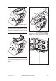
2. RIGGING SYSTEM 2.1 WARNING This manual contains needed information for flying D.A.S. Audio line array systems, description of the elements and safety precautions. To perform any operations related to flying the system, read the present document first, and act on the warnings and advice given. The goal is to the allow the user to become familiar with the mechanical elements required to fly the acoustic system, as well as the safety measures to be taken during set-up and teardown.
To facilitate the insertion of the connecting links in the corresponding slot of the top box, each angle has an associated pin hole which is labeled and located on each side of the box. Highly resistant 6mm quick release pins with a ball safety lock are used set the angles. 1º 6º 5º 7º 8º 10º 9º 4º 3º 2º 1º 4º 3º 2º 0º 0º 6º 5º 8º 7º 9º 10º Most of the accessories needed to fly or stack the units are integral to the enclosures. The only additional items needed are the rigging bumpers.
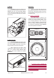
Truss M8x35 DIN912 screws Garra Hook Clamp The AXC-V25 ceiling mount accessory features several holes on the top plate which allow for hook clamps to be fixed to them, so up to 4 units can be flown from truss structures. The AXC-V25 can also be used to pole mount up to two units on top of one VARIANT 18A unit or on a tripod by making use of a special adaptor.
C) AXW-V25 E) Chain hoists The AXW-V25 is made from stainless steel and has been specially designed to wall mount up to 3 VARIANT 25A units. Six special M8x35 DIN912 screws must be used to attach the accessory to the wall. The whole cluster can be tilted as in the AXCV25 accessory. All units in a column will be flown from the AX-V25 rigging grid (bumper), which should be used with one hoist. The maximum load that can be flown using the AX-V25 is 285 kg (627 lb) so one 0.5 Ton hoist will be enough. 2.
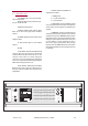
3. SELF POWERED SYSTEM 3.1 VARIANT 25A The VARIANT 25A is a two way class AB self powered system. Nominal amplifier power (Continuous) per way: LF:125 W HF:75 W Amplifier panel description: A) LIMIT: Amplifier limiter indicator lights. When lit, the level of the signal source should be reduced. B) SIGNAL: Signal presence indicator at the amplifiers' inputs. C) ON: Indicator light for each amplifier channel. D) FUSE. F) INPUT: Balanced signal XLR.
3.2 VARIANT 18A Low frequency mono-amplified system. Nominal amplifier power (Continuous) 1250 W. Amplifier panel description: A) LIMIT: Amplifier limiter indicator lights. When lit, the level of the signal source should be reduced. I A B C B) SIGNAL: Signal presence indicator at the amplifiers' inputs. H G F C) ON: Indicator light for each amplifier D channel. E D) FUSE. E) AC INPUT: With PowerCon NAC 3 FCA connector.
3.5 SWITCH ON-OFF 3.8 EQUALIZATION A sound system should be switched on sequentially. Switch on the self-powered unit last in your sound system. Switch on the sound sources such as CD players or turntables, then the mixer, then the processors, and finally the self-powered unit. If you have several units, it is recommended that you switch them on sequentially one at a time. Follow the inverse order when switching off, turning self-powered units off before any other element in the sound system.
SIGNAL INPUT SIGNAL INPUT SATELLITE OUTPUT SATELLITE OUTPUT 138 Hz POWER INPUT 138 Hz LINE POWER INPUT LINE Connection employing the filtered Satellite Output . POWER INPUT POWER INPUT SIGNAL INPUT SIGNAL INPUT Connection using an external processor to adjust the delay between systems.
3.11 TROUBLESHOOTING PROBLEM CAUSE SOLUTION No sound from the unit. The SIGNAL presence LED indicator(s) do(es) not light up. 1- The signal source is sending no signal. 1- Check that the mixer or sound source is sending signal to the UNIT. 2- Defective cable. 2- Check that the cable from the sound source to the UNIT is connected correctly. Replace the cable if defective. Full power cannot be obtained. The LIMIT LED indicator(s) never light(s) up.
4. SYSTEM INSTALLATION 4.1INTRODUCTION The VARIANT 25A unit can be installed in a number of ways. Typically several VARIANT 25A units would be assembled to form a line array cluster, but it can also be used alone, as a frontfill or as an underbalcony unit. A wide range of accessories and uses are available, and have been described in the paragraphs below. 4.
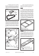
The procedure to mechanically connect the second unit is similar. First rotate the connecting links (5) in order to select the correct angle by means of the safety pins (6). In this example the selected angle is 2º. Once this has been done then the enclosure must be hung from the first box (7) and assured by means of one more safety pin (8). 3 4 2 1 7 Cluster of six VARIANT 25A. 8 The above described procedure applies to the rest of the units.
4.4 ASSEMBLING A SYSTEM WITH FLOWN SUBWOOFERS The VARIANT 18A units feature integral rigging hardware allowing them to be flown independently or above VARIANT 25A enclosures. -5º 0º 5º 0º VARIANT 18 AX-V25 1 VARIANT 25 The first step will be to mechanically connect the first VARIANT 18A to the AX-V25 grid. 6 safety pins are included in the rear side of the box in order to do so.
4.5 STACKING UNITS ON THE SUBS The VARIANT 18A units feature integral rigging hardware which can also be used for stacking VARIANT 25A units on top of them. The maximum recommended number of VARIANT 25A units in this mode is 6. The splay angles available between both enclosures are 0º, 5º and -5º. In order to attach the VARIANT 25A unit to the subwoofer unit, introduce the connecting (5) links on the VARIANT 18A into the receptacles on the VARIANT 25A.
4.6 SYSTEM INSTALLATION USING THE CEILING SUPPORT AXC-V25 The VARIANT 25A units can be set up as a long array of more than four enclosures (as explained above) or as a small array of 2, 3 or 4 units. In the latter case the highly resistant AX-V25 grid accessory is not necessary. Instead the AXC-V25 ceiling mount accessory can be used to hang a cluster of up to four units. Grower (lock) washer Metal washer First attach the ceiling mount accessory to the ceiling or a beam.
20º When a pair of hook clamps are attached to the ceiling mount accessory, it can be fixed to a truss structure such as the one shown in the picture below: The AXC-V25 accessory can also be used as a support for up to two VARIANT 25A units on a pole mount accessory, on top of one VARIANT 18A unit. To do so the AXC-V25 accessory is to be used upsidedown and a special pole mount adaptor must be fixed to it by means of two M8x35 DIN912 screws, nuts and washers.
4.7 SYSTEM INSTALLATION USING THE WALL SUPPORT AXW-V25 Up to three VARIANT 25A units can be wall mounted by means of the AXW-V25 accessory. Grower washer First the accessory must be fixed to the wall, making sure in advance that the work load of the wall allows for it. The wall mount accessory will be attached to the wall using six nº 10 rawlplugs and six 7 x 40 mm screws. Metal washer M8x35 DIN 912 Rubber washer Then hang the first VARIANT 25A unit from the wall mount accessory.
5. USING THE SYSTEM WITH SUBS When VARIANT 25A units are used in combination with VARIANT 18A subwoofers it is recommended to plug the mixer into the VARIANT 18A's input and then to connect the VARIANT 18A 138Hz high pass filtered output to the VARIANT 25A input. The ratio between VARIANT 25A and VARIANT 18A units that DAS Audio recommends to achieve a correct balance is 4:1 (As it depends on the kind of music and the application, it is subject to changes).
When using a subwoofer other than the VARIANT 18A in combination with the VARIANT 25A units, it is recommended that external processor be used to filter the signal fed into the VARIANT 25A units at 138 Hz. POWER INPUT SIGNAL INPUT 138 Hz LINE Delay 125 Hz 138 Hz AMPLIFIER SUB MODEL X If an externally amplified subwoofer unit is to be used in combination with VARIANT 25A satellites, the signal treatment will depend on the characteristics of the subwoofer used.
To remove the amplifier the enclosure has to bepositioned face downwards, on the aluminum front grill. Then remove the four M5x10 DIN965 screws that fix the amplifier to the sides of the box. 6. MAINTENANCE VARIANT 25A In order to access the 5B 5” speakers, the four M4x8 DIN965 screws that fix the aluminium grill to the box, should be removed. To replace the speakers, remove the four M4x20 DIN7985 screws.
VARIANT 18A In order to access the 18” 18H speaker, the six M4x8 DIN965 screws that fix the grille to the aluminum sides have to be removed first. Then remove the 8 M5x35 DIN7985 screws to replace the speaker. To access to the amplifier twelve M4x20 DIN965 screws that fix it to the rear side of the box must be removed.
7. SPECIFICATIONS MODEL VARIANT 25A LF Amplifier Power HF Amplifier Power Input Type Input Impedance Sensitivity Frequency Range (-10 dB) Horizontal Coverage (-6dB) Vertical Coverage Rated Maximum Peak SPL at 1 m Transducers/Replacement Parts Enclosure Geometry Enclosure Material Color/Finish Rigging System Splay Angles 250 Wpeak - 125 Wcontinuous 150 Wpeak - 75 Wcontinuous Balanced Differential Line Line: 20 kohms Line: 1.
APPENDIX. LINE CONNECTION: UN-BALANCED AND BALANCED. There are two basic ways to transport an audio signal with microphone or line level: Un-balanced line: Utilizing a two-conductor cable, it transports the signal as the voltage between them. Electro-magnetic interference can get added to the signal as undesired noise. Connectors that carry un-balanced signals have two pins, such as RCA ( Phono) and ¼” (6.35 mm, often referred to as jack) mono.
US/variant-00 D.A.S. AUDIO, S.A. C/. Islas Baleares, 24 - 46988 Fuente del Jarro - Valencia, SPAIN Tel. Intl. +34 96 134 0860 - Fax. Intl. +34 96 134 0607 D.A.S. AUDIO of AMERICA, Inc. Sunset Palmetto Park - 6816 NW 77th Court - Miami, FL 33166 U.S.A. TOLL FREE: 1-888DAS4USA Tel. 305 436 0521 D.A.S. AUDIO DEUTSCHLAND GmbH Frankfurter Straße 17 - 64546 Mörfelden-Walldorf Fon. +49 06105-967610 Fax 06105-96761 www.dasaudio.