
User`s manual


EN
8
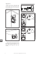
Remove screwRemove screw
Back out few turnsBack out few turns
2
1
Special screw M10x60Special screw M10x60
Slot
4
3
5
6
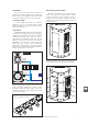
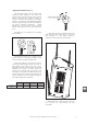
The vertical splay angle depends on the hole
where the quick release pin has been inserted (6).
The next step will be to secure the fixing
hardware part to the truss. In order to do so, the
nut and the wing nut must be tightened. Make
sure that the fixing hardware has been secured
tightly to the truss, and that it is not able to swing.
This way both parts of the rigging hardware will be
fixed: one to the truss and the other one to the
box.
Note: Maximum load capacity for is
50Kg. Never exceed this limit.
Once the fixing hardware has been attached to
the truss, then the box can be attached (5).
AX-TRUSS
Once the rear side screw has been removed,
the base of the will be placed on the
corner, making sure that the head of the upper
screw fits into the slot (3) on the base. Then the
special rear side screw, provided with the
hardware (4), will be fixed to the box.
AX-TRUSS
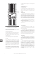
In order to attach the to the box,
firstly the screw on the upper rear side must be
backed out a few turns (1). Then the rear side
screw must be completely removed (2).
AX-TRUSS
Manual del Usuario / stage monitors / User’s Manual