Manual de Usuario / User’s Manual PS series Antes de utilizar el equipo, lea la sección “Precauciones de seguridad” de este manual. Conserve este manual para futuras consultas. Before operating the device, please read the “Safety precautions” section of this manual. Retain this manual for future reference.
PS
PS series Precauciones de Seguridad Safety Precautions Amplificadores de Potencia / Power Amplifiers Conserve y lea todas estas instrucciones. Siga todas las advertencias. El signo de exclamación dentro de un triángulo indica la existencia de componentes internos cuyo reemplazo puede afectar a la seguridad. Keep these instructions. Heed all warnings. Follow all instructions.
GARANTÍA Todos nuestros productos están garantizados por un periodo de 24 meses desde la fecha de compra. Las garantías sólo serán válidas si son por un defecto de fabricación y en ningún caso por un uso incorrecto del producto. Las reparaciones en garantía pueden ser realizadas, exclusivamente, por el fabricante o el servicio de asistencia técnica autorizado. Otros cargos como portes y seguros, son a cargo del comprador en todos los casos.
DECLARACIÓN DE CONFORMIDAD DECLARATION OF CONFORMITY D.A.S. Audio, S.A. C/ Islas Baleares, 24 - 46988 - Pol. Fuente del Jarro - Valencia. España (Spain).
Manual del Usuario / PS / User’s Manual
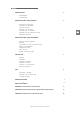
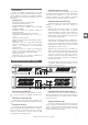
ÍNDICE 3 PRESENTACIÓN Generalidades Características DESCRIPCIÓN DEL PANEL FRONTAL 3 Interruptor de encendido Indicadores de encendido Controles de nivel Indicador LED de recorte Indicador LED de protección Indicador LED de presencia de señal Rejillas de ventilación DESCRIPCIÓN DEL PANEL POSTERIOR ES 4 Salida de línea de altavoces Entradas Conmutador de modo de funcionamiento Selector de sensibilidad Interruptor de tierra Cable de red Rejillas de entrada de aire 5 INSTALACIÓN Montaje Ventilación Cablea
ES Manual del Usuario / PS / User’s Manual
INTRODUCCIÓN Indicadores LED de recorte: (D) Cuando en alguno de los canales la señal supera la máxima tensión que puede suministrar la fuente de alimentación del amplificador, el LED rojo de ese canal se enciende. En este momento el limitador comienza a actuar corrigiendo el nivel de la señal. Generalidades Gracias por adquirir un amplificador D.A.S.
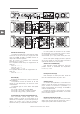
DESCRIPCIÓN DEL PANEL POSTERIOR PS-200, PS-400 HOT COLD CH B INPUT FOR CONTINUED PROTECTION AGAINST RISK OF FIRE, REPLACE ONLY WITH THE SAME FUSE TYPE C 3 GND 0.775V CH B ON N1918 1 D E B CH B INPUT 2 S.N. GROUND OFF G A CH B F PS-800, PS-1400 BRIDGE CH A 1.0V HOT COLD STEREO CH A INPUT SPEAKER OUTPUT SENSITIVITY GROUND 1.
INSTALACIÓN Montaje Los amplificadores están diseñados para montados en un rack estándar de 19 pulgadas. altura es de 2 unidades DIN en el caso de PS-800, 1400 y PS-2400, y de 1 unidad DIN en el caso de 200 y PS-400. ser Su PSPS- Para su montaje dispone de cuatro colisos (perforaciones alargadas) en la carátula, de los que puede ser sujeto al rack por tornillos de métrica cinco o seis.
USO Encendido / apagado El interruptor de encendido funcionamiento la etapa. pone en Al accionarlo (posición "|") se encenderán los led 'Protection', pocos segundos después, se producirá la activación de los canales del amplificador encendiéndose los led de 'ON' y apagándose los 'Protection' y la etapa estará lista para el funcionamiento. ES El apagado de la etapa se producirá actuando de nuevo sobre el interruptor de encendido (posición "0").
ESPECIFICACIONES Potencia EIA ambos canales / EIA Power, both channels driven (1 kHz @ 1% THD) 8 ohm, estéreo / stereo 4 ohm, estéreo / stereo 2 ohm, estéreo / stereo 8 ohm, puente / bridge PS-200 PS-400 PS-800 70 W 100 W ----200 W 140 W 200 W ----400 W 250 W 400 W ----800 W <0.
APÉNDICE A. Conexiones en modo puente El procedimiento para usar el amplificador en modo puente es el siguiente : 1. Apague el amplificador. 2. Baje al mínimo los dos controles de volumen. (Ambos atenuadores girados totalmente en sentido anti-horario). 3. Deberá entrar por la entrada XLR del canal A. 4. Seleccione el modo puente (BRIDGE) de la parte trasera del amplificador. 5.
APÉNDICE B. Conexiones balanceadas y no balanceadas Existen dos métodos básicos para transportar la señal de audio: Línea no-balanceada: Emplea un cable con dos conductores, transportando la señal como diferencia de potencial (voltaje) entre ambos. El ruido electromagnético (interferencias) del entorno puede sumarse a la señal que los cables transportan, apareciendo a la salida de nuestro sistema como ruido indeseado.
APÉNDICE C. Tabla para la selección del cable La pérdida de potencia y el factor de amortiguamiento resultante se muestran para varias longitudes y secciones de cable. Se recomienda un factor de amortiguamiento mínimo de 25, y preferiblemente no inferior a 50 para instalaciones de calidad.
CONTENTS 3 INTRODUCTION General Features FRONT PANEL DESCRIPTION 3 Power switch Power LED Input level controls Clip LED Protection LED Signal LED Cooling air outlet grilles BACK PANEL DESCRIPTION 4 Speaker outputs Inputs Input mode switch Input sensitivity selector Ground loop selector Mains LED Fan inlet grilles 5 INSTALLATION Racking Cooling Input cable connections Speaker cable connections Connetion to mains Current draw 6 USE Switch ON/OFF Clip LED Level controls SPECIFICATIONS 7 LINE DRAWINGS
EN Manual del Usuario / PS / User’s Manual
CLIP LED (D) In the event that the signal's excursion exceeds the maximum voltage from the power supply, the unit will indicate saturation through the clip LED of the channel involved. An automatic limiting system will impede prolonged saturation. INTRODUCTION General Thank you for purchasing a D.A.S. power amplifier. It has been built with the most advanced modular technology, and has been designed through the use of computer-aided design for both the electronic and mechanical parts.
REAR PANEL DESCRIPTION PS-200, PS-400 HOT COLD CH B INPUT FOR CONTINUED PROTECTION AGAINST RISK OF FIRE, REPLACE ONLY WITH THE SAME FUSE TYPE C 3 GND 0.775V CH B ON N1918 1 D E B CH B INPUT 2 S.N. GROUND OFF G A CH B F PS-800, PS-1400 BRIDGE CH A 1.0V HOT COLD STEREO CH A INPUT SPEAKER OUTPUT SENSITIVITY GROUND 1.
INSTALLATION Racking All amplifiers are 19-inch rack mount width. PS-200 and PS-400 are 1U DIN in height. PS-800, PS-1400 and PS-2400 are 2U DIN in height. Four front-panel mounting holes are provided for use with M5 or M6 or 1/4” screws. To avoid bending the chassis in rack mounting applications where the rack will be transported, mount the amplifiers to the back of the rack using the rear mounting holes.
USE Switch ON / OFF The main power switch turns the amplifier on. When the power switch is turned On ("|" position) the PROTECTION LED illuminates. After approximately 7 seconds the main power supply voltage will be turned on internally and the ON LEDs will illuminate. Then the PROTECTION LED will go out and the amplifier will be ready to be used. To turn the amplifier off push the power switch ("0" position).
SPECIFICATIONS Potencia EIA ambos canales / EIA Power, both channels driven (1 kHz @ 1% THD) 8 ohm, estéreo / stereo 4 ohm, estéreo / stereo 2 ohm, estéreo / stereo 8 ohm, puente / bridge PS-200 PS-400 PS-800 70 W 100 W ----200 W 140 W 200 W ----400 W 250 W 400 W ----800 W <0.
APPENDIX A. Bridge Mode Operation To operate in bridge mode, follow these steps: 1.Switch off the amplifier. 2.Turn volume control potentiometers on the front panel to minimum position (fully anticlockwise). 3.Connect input signal to channel A. 4.Set mode switch to “BRIDGE”. 5.Connect speakers as follows: Connect (+) to red speaker terminal on channel A's output terminals Connect (-) to red speaker terminal on channel B's output terminals 6.
APPENDIX B. Unbalanced and balanced connections There are two basic ways to transport an audio signal: Unbalanced line: Utilising a two-conductor cable, it transports the signal as the voltage between them. Electromagnetic interference can get added to the signal as undesired noise. Connectors that carry unbalanced signals have two pins, such as RCA (Phono) and 1/4” (6.35 mm, often referred to as jack) mono.
APPENDIX C. Table for cable selection The table below is intended to aid the selection of the appropriate cable. Power loss and resulting damping factor are shown for different values of cable length and area. A minimum damping factor of 25 is recommended, preferably not lower than 50 for quality installations.
UM_PS_01 www.dasaudio.com D.A.S. AUDIO, S.A. C/. Islas Baleares, 24 46988 Fuente del Jarro Valencia, SPAIN Tel. 96 134 0525 Tel. Intl. +34 96 134 0860 Fax 96 134 0607 Fax Intl. +34 96 134 0607 D.A.S. AUDIO OF AMERICA, INC. Sunset Palmetto Park 6816 NW 77th Court. Miami, FL. 33166 - U.S.A. TOLL FREE: 1-888DAS4USA Tel. +1 305 436 0521 Fax +1 305 436 0528 D.A.S. AUDIO ASIA PTE. LTD. 25 Kaki Bukit Crescent #01-00/02-00 Kaki Bukit Techpark 1 Singapore 416256 Tel.