
User`s manual
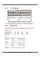
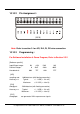


Jumper setting for 8254:
1-2 ON 2-3 ON
CLK0 T1 CLK0=TO_0 T1 CLK0=pin1 of J5
G0 T2 G0=always High T2 G0=pin2 of J5
OUT0 OUT0 to INT0 & pin3 of J5
CLK1 T4 CLK1=TO_1 T4 CLK0=pin4 of J5
G1 Always High
OUT1 OUT1 to T3.1 & T5.1 & T6.1
CLK2 T3 CLK2=OUT1 T3 CLK2=pin5 of J5
G2 Always High
OUT2 OUT2 to T5.3 & T7.1
T1 is used to select internal TO_0 or external signal for CLK0
T2 is used to select High or external signal for G0
T3 is used to control 16-bit/32-bit counter. 1-2 select 32-bits counter, 2-3
select two 16-bit counters
T4 is used to select internal TO_1 or external signal for CLK1
T5 is used to select OUT1 or OUT2 to INT1
T6 is used to select OUT1 to pin-7 of J5
T7 is used to select OUT2 to pin-8 of J5
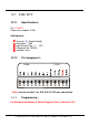
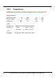
11.1.3 Programming :
For Software Installation & Demo Program, Refer to Section 2.2.2
I/O Expansion Bus for 7188X/7188E User’s Manual, Jun/2004 v1.4, 7PH-000-14---89