
User Manual


2
5) Easy to use: Panel use LCD to display the transmission frequency,
according to the identification of the interface to connect to other
hardware, easy to adjust and it is intuitive
6) Switching power: 100mW and 500mW power can be switched to use
7) Switching frequency: Can arbitrarily set from 76M to 108M range from
86M to 90M 95M to 108M, 87M to 108M
8) This subsection is with a microphone and volume control
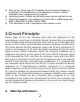
3.Circuit Principle:
Stereo audio via 3.5 mm interface input, after the adjustment of the
potentiometer control input to BH1415 internal, internal after pre-emphasis
circuit, limiting circuit and low-pass filter circuit and by 13, 14 feet again after
access to the 7.6 MHz crystal vibration frequency oscillation circuit through
200 points after the 38 KHZ subcarrier signal, and 38 KHZ subcarrier by 2
points in the frequency of 19 KHZ pilot signal modulation.Firstly, the audio
signal and the 38KHz subcarrier signal are balanced modulated by a
multiplexer to produce a main signal (L+R) and a 38KHz subcarrier signal
(L-R) modulated by DSB, and then the composite signal with the 19KHz
pilot signal is output from the 5th leg.The microphone audio is also input by
another 3.5mm interface, and after audio amplification, it is combined with
the composite signal output from the 5th pin. The two channels are directly
modulated by a high-frequency oscillator composed of a variogram
diode.Frequency control by touch the key and the MCU control the internal
PLL circuit to stabilize the transmission frequency.After two stages of power
amplification, the transmitting frequency generates 800MW power output,
which is then filtered out by a low-pass filter composed of LC and
transmitted to the antenna for transmission.The MCU then transmits the
current transmission frequency information to the user in real time through
the LCD display module.
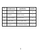
4. Main Specifications: