
User Manual


ROBOT.HEADtoTOE
ProductUser’sManual–MDDS60
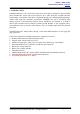
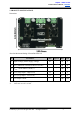
FUNCTIONDescription:
MotorLEFTTerminalBlock
Connect to motor LEFT at your mobile robot. User can screw to lock the wire to the terminal
block or solder the wire directly to the pad at bottom layer. Please use wire with proper
thicknesstosupporttheexpectedcurrent.
PowerSupplyTerminalBlock
Connecttopowersource.Usercanscrewtolockthewiretotheterminalblockorsolderthe
wiredirectlytothepadatbottomlayer.Nopolarityprotection,pleasedoublecheckbefore
powerup.Pleaseusewirewithproperthicknesstosupporttheexpectedcurrent.
MotorRIGHTTerminalBlock
Connect to motor RIGHT at your mobile robot. User can screw to lock the wire to the
terminal block or solder the wire directly to the pad at bottom layer. Please use wire with
properthicknesstosupporttheexpectedcurrent.
MotorLEFTLEDIndicator
Indication for current flow and direction for motor LEFT. If LED MLA turns on, means
currentflowsfromoutputMLAtoMLB.Viceversa.
MotorRIGHTLEDIndicator
IndicationforcurrentflowanddirectionformotorRIGHT.IfLEDMRAturnson,means
currentflowsfromoutputMRAtoMRB.Viceversa.
PowerSwitchTerminalBlock
Switch for power up MDDS60’s microcontroller and logic circuit. This switch is ON by
default.UserneedtocutthePCBtrackatthebottomlayerofPCBtoutilizethisterminal.
CoolingFan
OnceMDDS60ispoweredup,thisfanwillblowtheboard.
RunandErrorLED
RUN_L: Turns on when motor LEFT is running. If signal error received for motor LEFT, it
willblink.
RUN_R: Turns on when motor RIGHT is running. If signal error received for motor RIGHT,
itwillblink.
CreatedbyCytronTechnologiesSdn.Bhd.–AllRightsReserved 7