
Manual


ROBOT.HEAD to TOE
Product User’s Manual - MDDS30
Created by Cytron Technologies Sdn Bhd – All Rights Reserved
Back to INDEX 8
F
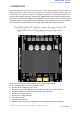
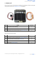
COOLING FAN CONNECTOR
Optional cooling fan (not included) can be connected here and mount at the bottom PCB.
G
HEAT SINK
This area might be hot, please be careful.
H
RIGHT CHANNEL LED INDICATOR
RUN - Turns on when motor RIGHT is running. If signal error received for motor RIGHT, it will
blink.
ERR - Blinks at specific count if there have an error.
OC - Light up if overcurrent happened.
I
LEFT CHANNEL LED INDICATOR
RUN - Turns on when motor LEFT is running. If signal error received for motor LEFT, it will blink.
ERR - Blinks at specific count if there have an error.
OC - Light up if overcurrent happened.
J
POWER LED INDICATOR
Indication for board’s power.
K
MOTOR LEFT TEST BUTTON
Fast test to check driver functionality for motor LEFT. If MLA is pressed, current flows from
output MLA to MLB. Vice Versa.
L
MOTOR RIGHT TEST BUTTON
Fast test to check driver functionality for motor RIGHT. If MRA is pressed, current flows from
output MRA to MRB. Vice Versa.
M
RC INPUT PIN
This pins specially for RC receiver input wire. RC1 for forward/reverse and RC2 for steering.
N
ANALOG/PWM INPUT PIN (GROVE)
AN1 - Analog/PWM signal for motor LEFT.
AN2 - Analog/PWM signal for motor RIGHT.
O
DIGITAL/SERIAL INPUT PIN (GROVE)
IN1 - Digital signal (direction) for motor LEFT, or can be used for Serial mode.
IN2 - Digital signal (direction) for motor RIGHT.
P
MODE SELECTION DIP SWITCH
User can select different input mode by setting the DIP switch.
Q
RESET BUTTON
Press this button will restart the system. This is useful if you want to change mode without
recycle power (turn off and on).