
Manual


ROBOT.HEAD to TOE
Product User’s Manual - MDDS30
Created by Cytron Technologies Sdn Bhd – All Rights Reserved
Back to INDEX 23
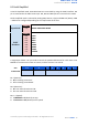
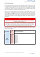
A packet consists of 4 bytes and the format is shown in the following table.
BYTE
NAME
VALUE
(Decimal)
DESCRIPTION
1
Header
85
To indicate the start of packet.
2
Channel &
Address
Channel:
Bit 3
Address:
Bit 0 - 2
Used to identify the driver when multiple units are
connected together. The Address bits (bit 2 - 0)
must match the address configured with the DIP
switch. Bit 3 represent which motor to be
controlled (0 for motor LEFT and 1 for motor
RIGHT). Bit 4 - 7 is not used.
3
Command
0 - 255
Value 127 stops the motor, 0 is full reverse and 255
is full forward.
4
Checksum
0 - 255
The value for checksum must be the result of
Header + Address + Command.
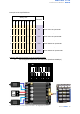
Common DIP switch settings for Serial Packetized mode
● Serial Packetized mode with microcontroller (Address: 0)
ON
1
2
3
4
5
6
7
8
*Sample connection for MDDS30 with CT UNO (or Arduino/Genuino Uno) and Base Shield
V2. This connection is recommended for beginner.