
Manual


ROBOT.HEAD to TOE
Product User’s Manual - MDDS30
Created by Cytron Technologies Sdn Bhd – All Rights Reserved
Back to INDEX 22
8.4 Serial Packetized
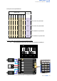
In Serial Packetized mode, SmartDriveDuo-30 is controlled by using the UART interface. IN1
pin is connected to the UART receive pin. IN2, AN1 and AN2 pins are not used in this mode.
To control the motor, data sent to the driver must be in 4 bytes packet format which
includes a header, address, command and checksum. Up to 8 units of SmartDriveDuo-30 can
be connected together to a single microcontroller UART Tx pin.
Besides that, the SmartDriveDuo-30 also incorporates an auto-baudrate feature in this
mode. When the driver is powered up, the host microcontroller must send a dummy byte
(Decimal 128 or Hex 0x80) once to the driver. The driver will then calculate the baudrate
automatically based on this byte. After that, SmartDriveDuo-30 is ready to read full packet
(4 bytes) and the baudrate cannot be changed without power recycle (power off and on) or
reset button.
NOTE
When the driver is powered up and waiting for the header byte, the error LED will blink
and indicate that there is input error.
SmartDriveDuo-30 may take up to 500ms to start up after power is applied. Sending a
dummy byte for auto-baudrate during this period may cause undesirable results. Please
allow one-second delay between applying power and sending a dummy byte.
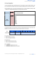
Packetized Serial mode is selected by setting SW1, SW2 and SW3 to 1 (Up). SW4 – SW6 are
used to select the address.
Input Mode
SW1-SW3
111
SERIAL PACKETIZED MODE
UART
Address
SW4-SW6
000
001
010
011
100
101
110
111
Address: 0
Address: 1
Address: 2
Address: 3
Address: 4
Address: 5
Address: 6
Address: 7
0 - OFF 1 - ON X - Don’t care