
Manual


ROBOT.HEAD to TOE
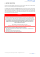
Product User’s Manual - MDDS30
Created by Cytron Technologies Sdn Bhd – All Rights Reserved
Back to INDEX 12
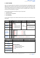
8. INPUT MODES
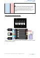
When the SmartDriveDuo-30 is powered up, RUN (Left), ERR (Left), RUN (Right) and ERR
(Right) LEDs will running once. After that, the input mode will be read from the DIP switch
and retained as long as the driver is powered. If you wish to change the input mode, you will
need to change the setting on the DIP switch and press the RESET button, or power cycle
the driver (turn it off and turn it on again).
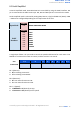
SmartDriveDuo-30 supports four different types of input mode:
1. RC (Radio Control).
2. Microcontroller Analog/PWM.
3. Serial Simplified.
4. Serial Packetized.
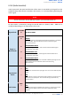
The DIP switch settings for each mode and the function for input pin are summarized on the
table below.
DIP Switch
1
2
3
4
5
6
RC
0
0
CHANNEL
00 - Mixed
01 - Independent Right
10 - Independent Left
11 - Independent Both
0 - Linear
1 - Exponential
0 - RC
1 - MCU
Analog
0
1
0 - Locked Anti-Phase
1 - Signed Magnitude
PWM
1
0
Serial
Simplified
1
1
0
BAUDRATE
000 - 1200
001 - 2400
010 - 4800
011 - 9600
100 - 19200
101 - 38400
110 - 57600
111 - 115200
Serial
Packetized
1
1
1
ADDRESS
Start from 000 (Decimal: 0) to 111 (Decimal: 7)
DIP Switch
7
8
RC
BATTERY MONITOR
00 - LiPo (Lithium Polymer)
01 - NiMH (Nickel-Metal Hydride)
10 - SLA (Sealed Lead Acid)
11 - Off
Analog
PWM
Serial Simplified
Serial Packetized