SmartDriveDuo-30 MDDS30 User’s Manual Rev 1.0 April 2017 Information contained in this publication regarding device applications and the like is intended through suggestion only and may be superseded by updates. It is your responsibility to ensure that your application meets with your specifications.
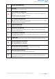
ROBOT.HEAD to TOE Product User’s Manual - MDDS30 INDEX PAGES 1. INTRODUCTION 2 2. PACKING LIST 3 3. PRODUCT SPECIFICATIONS 4 4. BOARD LAYOUT 6 5. POWER SUPPLY 6. MOTOR CONNECTION 7. SAFETY FEATURES 8. INPUT MODES 8.1. RC (Radio Control) 8.2. Microcontroller Analog/PWM 8.3. Serial Simplified 8.4. Serial Packetized 9.
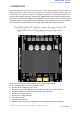
ROBOT.HEAD to TOE Product User’s Manual - MDDS30 1. INTRODUCTION SmartDriveDuo-30 is one of the latest smart series motor drivers designed to drive medium power brushed DC motor with current capacity up to 80A peak (few seconds) and 30A continuously, each channel. This driver is designed specially for controlling differential drive mobile robot using RC controller. Nevertheless, MDDS30 also can be controlled using analog joystick or microcontroller (PWM, Serial).
ROBOT.HEAD to TOE Product User’s Manual - MDDS30 ● On board push buttons for fast test and manual operation. ● NO POLARITY PROTECTION FOR V MOTOR.
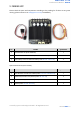
ROBOT.HEAD to TOE Product User’s Manual - MDDS30 2. PACKING LIST Please check the parts and components according to the packing list. If there are any parts missing, please contact us at sales@cytron.com.my immediately.
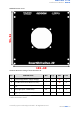
ROBOT.HEAD to TOE Product User’s Manual - MDDS30 3. PRODUCT SPECIFICATIONS Dimension (unit in mm): ● MDDS30 main board. ● MDDS30 height.
ROBOT.HEAD to TOE Product User’s Manual - MDDS30 MDDS30 bottom cover: Absolute Maximum Rating of SmartDriveDuo-30: No PARAMETERS Min Typ Max Unit 1 Input Voltage (Motor Supply Voltage) 7 – 35 V 2 IMAX (Max Continuous Motor Current)* – – 30 A 3 IPEAK (Peak Motor Current)** – – 80 A 4 VIOH (Logic Input – HIGH Level) 1.3 – 5 V 5 VIOL (Logic Input – LOW Level) 0 – 0.7 V *Depends on the room temperature. **Must not exceed 1 second.
ROBOT.HEAD to TOE Product User’s Manual - MDDS30 4. BOARD LAYOUT LABEL FUNCTION A MOTOR RIGHT LED INDICATOR B MOTOR RIGHT TERMINAL BLOCK C D E Indication for current flow and direction for motor RIGHT. If LED MRA turns on, means current flows from output MRA to MRB. Vice versa. Connect to motor RIGHT at your mobile robot. User can screw to lock the wire to the terminal block. Please use wire with proper thickness to support the expected current.
ROBOT.HEAD to TOE Product User’s Manual - MDDS30 F COOLING FAN CONNECTOR G HEAT SINK Optional cooling fan (not included) can be connected here and mount at the bottom PCB. This area might be hot, please be careful. RIGHT CHANNEL LED INDICATOR H I RUN - Turns on when motor RIGHT is running. If signal error received for motor RIGHT, it will blink. ERR - Blinks at specific count if there have an error. OC - Light up if overcurrent happened.
ROBOT.HEAD to TOE Product User’s Manual - MDDS30 5. POWER SUPPLY SmartDriveDuo-30 supports battery with input voltage ranges from 7V to 35V. The recommended power sources are: ● 6 – 18 cells NiMH or NiCd battery. ● 3 – 6 cells LiPo or Li-Ion battery. ● 7V – 35V sealed lead acid battery. ● 7V – 35V power supply. MUST BE IN PARALLEL WITH A BATTERY WITH SAME VOLTAGE The power source can be connected to SmartDriveDuo-30 either via the terminal block, or soldered directly to the pad at the bottom layer.
ROBOT.HEAD to TOE Product User’s Manual - MDDS30 6. MOTOR CONNECTION Similar to the power supply, connection to the motor can be made either via the terminal block, or it can be soldered directly to the bottom layer pad. For MIXED mode, especially for RC input mode, each terminal block must be connected to the same side of the motor. For example, left terminal block connected to motor LEFT and right terminal block connected to motor RIGHT.
ROBOT.HEAD to TOE Product User’s Manual - MDDS30 7. SAFETY FEATURES SmartDriveDuo-30 incorporates some safety features which make it robust and reliable motor driver. Below are the detailed descriptions for each feature. 1. Input Error (Error LED blinks 2 times) Every time SmartDriveDuo-30 is power up, the input data must be ‘stop’ (for RC, Analog, PWM input mode). This feature prevent the driver from sudden run, especially when the driver accidently reset. 2.
ROBOT.HEAD to TOE Product User’s Manual - MDDS30 8. INPUT MODES When the SmartDriveDuo-30 is powered up, RUN (Left), ERR (Left), RUN (Right) and ERR (Right) LEDs will running once. After that, the input mode will be read from the DIP switch and retained as long as the driver is powered. If you wish to change the input mode, you will need to change the setting on the DIP switch and press the RESET button, or power cycle the driver (turn it off and turn it on again).
ROBOT.
ROBOT.HEAD to TOE Product User’s Manual - MDDS30 8.1 RC (Radio Controlled) In RC input mode, the speed and direction of the motor is controlled by the signal from the standard hobby radio control transmitter and receiver, or a microcontroller generating the similar signal. NOTE The RC transmitter must be ON before power up the SmartDriveDuo-30. RC Input mode is selected by setting the SW1 & SW2 to 0 (Down). SW3 – SW6 can be configured depending on the requirement of the user.
ROBOT.HEAD to TOE Product User’s Manual - MDDS30 1 ON The center point is fixed at 1.5ms and the timeout feature is disabled. Motor will continue to run with previous speed if new signal is not detected. This is useful when a microcontroller is used to control the motor. The microcontroller does not need to send the pulse continuously to the SmartDriveDuo-30. Instead, it only needs to send a single pulse when the speed or direction of the motor needs to be changed.
ROBOT.HEAD to TOE Product User’s Manual - MDDS30 ● RC Mode with microcontroller (Independent Both) ON 1 2 3 4 5 6 7 8 *Sample connection for MDDS30 with CT UNO (or Arduino/Genuino Uno) and Base Shield V2. This connection is recommended for beginner. **Arduino Uno sample code is provided at the following link - GitHub.
ROBOT.HEAD to TOE Product User’s Manual - MDDS30 8.2 Microcontroller Analog/PWM In Analog/PWM input mode, the speed and direction of the motor is controlled by the analog voltage or PWM signal. For analog, the valid input range is from 0 to 5V. While for PWM, it can accept TTL PWM from 1.3 to 5V for HIGH level (refer to Product Specifications). NOTE The Analog/PWM signal to stop the motor must be available when SmartDriveDuo-30 is turned on/reset.
ROBOT.HEAD to TOE Product User’s Manual - MDDS30 The speed is linear with the input signal. This is for low to medium speed motor. 1 ON The response to input is exponential and thus soften the control around the center zero speed point. This is suitable for high speed and very sensitive motor. SW6 0 LOCKED ANTI-PHASE Motor stops when the input signal is 2.5V. Motor moves in one direction when the input is < 2.5V (0 - 2.5V) and in another direction when the input is > 2.5V (2.5 - 5V).
ROBOT.HEAD to TOE Product User’s Manual - MDDS30 8.3 Serial Simplified In Serial Simplified mode, SmartDriveDuo-30 is controlled by using the UART interface. IN1 pin is connected to the UART receive pin. IN2, AN1 and AN2 pins are not used in this mode. Serial Simplified mode is selected by setting SW1, SW2 to 1 (Up) and SW3 to 0 (Down). SW4 – SW6 can be configured depending on the requirement of the user.
ROBOT.HEAD to TOE Product User’s Manual - MDDS30 Example Serial Simplified data: Binary bits Decimal 7 6 5 4 3 2 1 0 1. 0 0 0 0 0 0 0 0 0 2. 0 0 1 1 1 1 1 1 63 motor LEFT full speed CW. 3. 0 1 0 0 0 0 0 0 64 motor LEFT stop. 4. 0 1 1 1 1 1 1 1 127 motor LEFT full speed CCW. 5. 1 0 0 0 0 0 0 0 128 motor RIGHT stop. 6. 1 0 1 1 1 1 1 1 191 motor RIGHT full speed CW. 7. 1 1 0 0 0 0 0 0 192 motor RIGHT stop. 8.
ROBOT.HEAD to TOE Product User’s Manual - MDDS30 *Sample connection for MDDS30 with CT UNO (or Arduino/Genuino Uno) and Base Shield V2. This connection is recommended for beginner. **Arduino Uno sample code is provided at the following link - GitHub.
ROBOT.HEAD to TOE Product User’s Manual - MDDS30 8.4 Serial Packetized In Serial Packetized mode, SmartDriveDuo-30 is controlled by using the UART interface. IN1 pin is connected to the UART receive pin. IN2, AN1 and AN2 pins are not used in this mode. To control the motor, data sent to the driver must be in 4 bytes packet format which includes a header, address, command and checksum. Up to 8 units of SmartDriveDuo-30 can be connected together to a single microcontroller UART Tx pin.
ROBOT.HEAD to TOE Product User’s Manual - MDDS30 A packet consists of 4 bytes and the format is shown in the following table. BYTE NAME VALUE (Decimal) 1 Header 85 DESCRIPTION To indicate the start of packet. Used to identify the driver when multiple units are connected together. The Address bits (bit 2 - 0) must match the address configured with the DIP switch. Bit 3 represent which motor to be controlled (0 for motor LEFT and 1 for motor RIGHT). Bit 4 - 7 is not used.
ROBOT.HEAD to TOE Product User’s Manual - MDDS30 **Arduino Uno sample code is provided at the following link - GitHub.
ROBOT.HEAD to TOE Product User’s Manual - MDDS30 9. WARRANTY ● ● ● ● Product warranty is valid for 12 months. Warranty only applies to manufacturing defect. Damaged caused by misuse is not covered under warranty. Warranty does not cover freight cost for both ways. Prepared by: Cytron Technologies Sdn Bhd www.cytron.com.my No. 1, Lorong Industri Impian 1, Taman Industri Impian, 14000 Bukit Mertajam, Penang, Malaysia.
ROBOT.HEAD to TOE Product User’s Manual - MDDS30 support@cytron.com.my sales@cytron.com.