
Manual

ROBOT . HEAD to TOE
Product User’s Manual – MDDS10
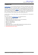
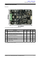
FUNCTION Description:
Motor RIGHT LED Indicator
Indication for current flow and direction for motor RIGHT. If LED MRA turns on, means
current flows from output MRA to MRB. Vice versa.
Motor RIGHT Terminal Block
Connect to motor RIGHT at your mobile robot. User can tie the wire to the terminal block or
solder the wire directly to the pad at bottom layer.
Power Supply Terminal Block
Connect to power source. User can tie the wire to the terminal block or solder the wire
directly to the pad at bottom layer. No polarity protection, please double check before
power up.
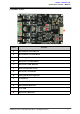
Motor LEFT Terminal Block
Connect to motor LEFT at your mobile robot. User can tie the wire to the terminal block or
solder the wire directly to the pad at bottom layer.
Motor LEFT LED Indicator
Indication for current flow and direction for motor LEFT. If LED MLA turns on, means
current flows from output MLA to MLB. Vice versa.
Mode Selection DIP Switch
User can select different input mode by setting the DIP switch.
Motor LEFT Test Button
Fast test to check driver functionality for motor LEFT. If MLA is pressed, current flows from
output MLA to MLB. Vice Versa.
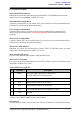
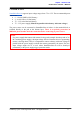
Analog/PWM/Serial Input Pin
No
Pin Name
Description
1
DIG1*
1: Digital signal (Direction) for motor LEFT.
2: Serial Simplified, Serial Packetized.
2
DIG2
Digital signal (Direction) for motor RIGHT.
3
AN1
Analog/PWM signal for motor LEFT.
4
AN2
Analog/PWM signal for motor RIGHT.
5
+5V
+5V output. Do not connect to another 5V source.
6
GND
Ground.
*DIG1 can accept 2 types of input.
**Please refer to INPUT MODE section for more detail.
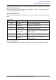
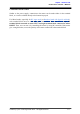
RC Input Pin
This pins specially for RC receiver input wire. RC1 for forward/reverse and RC2 for steering.
Created by Cytron Technologies Sdn. Bhd. – All Rights Reserved 7