
Manual


ROBOT . HEAD to TOE
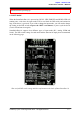
Product User’s Manual – MDDS10
8.4 SERIAL PACKETIZED MODE
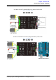
In Packetized Serial mode, SmartDriveDuo-10 is controlled by using the UART interface.
DIG1 pin is the UART Rx pin. DIG2, AN1 and AN2 pins are not used in this mode. To
control the motor, data sent to the driver must be in 4 bytes packet format which includes a
header, address, command and checksum. Up to 8 units of SmartDriveDuo-10 can be
connected together to a single microcontroller UART Tx pin.
Besides that, the SmartDriveDuo-10 also incorporates an Auto-Baud feature in Packetized
Serial mode. When the driver is first powered up, the host microcontroller must send a header
byte (Decimal 85 or hex 55) once to the driver. The driver will then calculate the baud rate
automatically based on this byte. After that, SmartDriveDuo-10 is ready to read full packet (4
bytes) and the baud rate cannot be changed without power recycle (power off and on) or reset
button.
NOTE:
1. When the driver is powered up and waiting for the header byte, the error LED will
blink and indicate that there is input error.
2. SmartDriveDuo-10 may take up to 500ms to start up after power is applied. Sending
the header byte for auto baud during this time period may cause undesirable results.
Please allow one-second delay between applying power and sending the header byte.
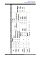
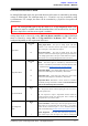
Packetized Serial mode is selected by setting SW1, SW2 and SW3 to 1 (Up). SW4 – SW6
are used to select the address.
Input Mode
SW1 - SW3
111
Packetized Serial Mode
UART Address
SW4 - SW6
000 - 111
0 - 7
0 - OFF 1 - ON X - Don’t Care
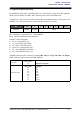
A packet consists of 4 bytes and the format is shown in the following table.
Byte
Name
Value (Decimal)
Description
1
Header
85
To indicate the start of packet.
2
Channel &
Address
Channel: Bit 3
Address: Bit 2 - 0
Used to identify the driver when multiple units are connected
together. The address bits (bit 2 - 0) must match the address
configured with the DIP switch. Bit 3 represent which motor
to be controlled, 0 for motor LEFT and 1 for motor RIGHT.
3
Command
0 – 255
Value 127 stops the motor, 0 is full reverse and 255 is full
forward.
4
Checksum
0 – 255
The value for checksum must be the result of
Header + Address + Command
Created by Cytron Technologies Sdn. Bhd. – All Rights Reserved 20