
Manual


ROBOT . HEAD to TOE
Product User’s Manual – MDDS10
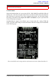
8.2 ANALOG/PWM INPUT MODE
In Analog/PWM input mode, the speed and direction of the motor is controlled by the analog
voltage or PWM signal. The valid input range is 0 – 5V and it’s very easy to control by using
a potentiometer. For example, the motor can be controlled by a joystick or foot pedal with
potentiometer.
NOTE: The Analog/PWM signal to stop the motor (2.5V if Sign-Magnitude mode is off,
0V otherwise) must be available when the SmartDriveDuo-10 is turned on. Else, the driver
will show Input Error until the correct signal is available.
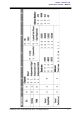
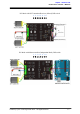
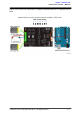
Analog input mode is selected by setting SW1 to 0 (Down) and SW2 to 1 (Up). PWM input
mode is selected by setting SW1 to 1 (Up) and SW2 to 0 (Down). SW3 – SW6 can be
configured depending on the requirement of the user.
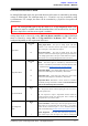
Input Mode
SW1:SW2
01
10
Analog Input Mode – The input is analog signal. The filter
capacitor is not connected and the input signal is not filtered.
SW1 is for Input 1 while SW2 is for Input 2.
PWM Input Mode – The input is PWM signal. The filter
capacitor is connected and the input signal is low pass filtered to
be an analog signal. SW1 is for Input 1 while SW2 is for Input 2.
SW2 must be set to 0 if Sign-Magnitude mode is turned on.
Single/Mix Mode
SW3:SW4
00
01
10
11
Mixed – The motor speed is controlled by channel RC1 and
direction is controlled by channel RC2. Recommended this mode
if controlled using Breakout board with Joystick soldered.
Independent Right – Only motor Right will active, motor Left
will inactive. Motor Right is controlled by channel RC2.
Independent Left – Only motor Left will active, motor Right
will inactive. Motor Right is controlled by channel RC1.
Independent Both - Both motor is active and can be controlled
individually through channel RC1 and RC2. Recommended this
mode if controlled using Microcontroller.
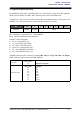
Exponential Mode
SW5
0
1
Off – The speed is linear with the input signal. This is for low to
medium speed motor.
On –The response to input is exponential and thus soften the
control around the center zero speed point. This is suitable for
high speed and very sensitive motor.
Sign-Magnitude
Mode
SW6
0
1
Locked Anti-Phase – Motor stops when the input signal is 2.5V.
Motor moves in one direction when the input is < 2.5V and in
another direction when the input is > 2.5V. Recommended this
mode if controlled using Breakout board with Joystick soldered.
Signed Magnitude – AN1 and AN2 controls the speed of the
motor. Motor stops when the input is 0V and run at full speed
Created by Cytron Technologies Sdn. Bhd. – All Rights Reserved 16