
Data Sheet


ROBOT.HEADtoTOE
ProductUser’sManual–MDS40B
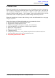
FUNCTIONDescription:
MotorTerminalBlock
Connect to motor at your mobile robot. User can screw to lock the wire to the terminal block
or solder the wire directly to the pad at bottom layer. Please use wire with proper thickness to
supporttheexpectedcurrent.
PowerSupplyTerminalBlock
Connecttopowersource.Usercanscrewtolockthewiretotheterminalblockorsolderthe
wiredirectlytothepadatbottomlayer.Nopolarityprotection,pleasedoublecheckbefore
powerup.Pleaseusewirewithproperthicknesstosupporttheexpectedcurrent.
MotorLEDIndicator
Indication for current flow and direction for motor. If LED A turns on, means current flows
fromoutputAtoB.Viceversa.
PowerSwitchTerminalBlock
Switch for power up MDS40B’s microcontroller and logic circuit. This switch is ON by
default.
RunandErrorLED
RunLEDwillturnonwhenmotorisrunning.
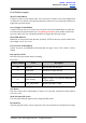
ErrorLED
NumberofBlinks
Error
Description
Off
NoError
Noerrorhasbeendetected.
2
InputError
Invalidornoinputdetected.
3
UnderVoltage
Thebatteryvoltageislow.
4
OverVoltage
Supplyvoltageisoverthelimit.MDS40B
willnotoperate.
5
OverTemperature
Boardtemperatureishigh.
TestButton
Fast test to check driver functionality for motor. If A is pressed, current flows from output A
toB.ViceVersa.
ModeSelectionDIPSwitch
UsercanselectdifferentinputmodebysettingtheDIPswitch.
RCInputPin
ThispinsspeciallyforRCreceiverinputwire.RC1forforward/reverseandRC2forsteering.
CreatedbyCytronTechnologiesSdn.Bhd.–AllRightsReserved 7