
Data Sheet


ROBOT.HEADtoTOE
ProductUser’sManual–MDS40B
8.2ANALOG/PWMINPUTMODE
In Analog/PWM input mode, the speed and direction of the motor is controlled by the analog
voltage or PWM signal. The valid input range is 0 – 5V and it’s very easy to control by using
a potentiometer. For example, the motor can be controlled by a joystick or foot pedal with
potentiometer.
NOTE: The Analog/PWM signal to stop the motor (2.5V if SignMagnitude mode is off,
0V otherwise) must be available when the Enhanced SmartDrive40 is turned on. Else, the
driverwillshowInputErroruntilthecorrectsignalisavailable.
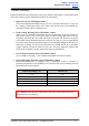
Analog input mode is selected by setting SW1 to 0 (Down) and SW2 to 1 (Up). PWM input
mode is selected by setting SW1 to 1 (Up) and SW2 to 0 (Down). SW3 – SW6 can be
configureddependingontherequirementoftheuser.
InputMode
SW1:SW2
01
10
Analog Input Mode – The input is analog signal. The filter
capacitor is not connected and the input signal is not filtered.
SW1isforInput1whileSW2isforInput2.
PWM Input Mode – The input is PWM signal. The filter
capacitor is connected and the input signal is low pass filtered
to be an analog signal. SW1 is for Input 1 while SW2 is for
Input 2. SW2 must be set to 0 if SignMagnitude mode is turned
on.
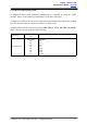
Single/MixMode
SW3:SW4
00
10
11
Independent – The motor speed and direction are controlled by
a single channel connected to Input 1. Motor stops when the
input signal is at the center point. Input 2 is not used in this
mode.
Mixed Right – This mode should be selected for the right motor
of the robot differential drive system. Input 1 controls the
overall speed as well as forward/backward movement of the
robot. Input 2 controls the left/right or pivot movement of the
robot. In right mix mode, the motor will be slowed down when
the robot is commanded to turn right and vice versa. SW8 must
besetto0.
Mixed Left – This mode should be selected for the left motor of
the robot differential drive system. Input 1 controls the overall
speed as well as forward/backward movement of the robot. Input
2 controls the left/right or pivot movement of the robot. In left
mix mode, the motor will be slowed down when the robot is
commandedtoturnleftandviceversa.SW8mustbesetto0.
ExponentialMode
SW5
0
1
Off – The speed is linear with the input signal. This is for low to
mediumspeedmotor.
On –The response to input is exponential and thus soften the
control around the center zero speed point. This is suitable for
highspeedandverysensitivemotor.
CreatedbyCytronTechnologiesSdn.Bhd.–AllRightsReserved 17