
Data Sheet


ROBOT.HEADtoTOE
ProductUser’sManual–MDS40B
8.1RCINPUTMODE
In RC input mode, the speed and direction of the motor is controlled by the signal from the
standard hobby radio control transmitter and receiver, or a microcontroller generating the
similarsignal.
NOTE:TheRCtransmittermustbeONbeforepoweruptheEnhancedSmartDrive40.
RC Input mode is selected by setting the SW1 & SW2 to 0 (Down). SW3 – SW6 can be
configureddependingontherequirementoftheuser.
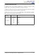
InputMode
SW1:SW2
00
RCInputMode
Single/MixMode
SW3:SW4
00
10
11
Independent – The motor speed and direction are controlled by a
single RC channel connected to Input 1. Motor stops when the input
signalisatthecenterpoint.Input2isnotusedinthismode.
Mixed Right – This mode should be selected for the right motor of the
robot differential drive system. Input 1 controls the overall speed as
well as forward/backward movement of the robot. Input 2 controls the
left/right or pivot movement of the robot. In right mix mode, the motor
will be slowed down when the robot is commanded to turn right and
viceversa.
Mixed Left – This mode should be selected for the left motor of the
robot differential drive system. Input 1 controls the overall speed as
well as forward/backward movement of the robot. Input 2 controls the
left/right or pivot movement of the robot. In left mix mode, the motor
will be slowed down when the robot is commanded to turn left and
viceversa.
ExponentialMode
SW5
0
1
Off – The speed is linear with the input signal. This is for low to
mediumspeedmotor.
On –The response to input is exponential and thus soften the control
around the center zero speed point. This is suitable for high speed and
verysensitivemotor.
MCUMode
SW6
0
1
Off – The center point will be calibrated upon power up. Timeout
occurs after lost of signal for 100ms and the motor will be stopped for
safetypurpose.
On – The center point is fixed at 1.5ms and the timeout feature is
disabled. Motor will continue to run with previous speed if new signal
is not detected. This is useful when a microcontroller is used to control
the motor. The microcontroller does not need to send the pulse
continuously to the Enhanced SmartDrive40. Instead, it only needs to
send a single pulse when the speed or direction of the motor needs to
bechanged.
0–OFF 1–ON X–Don’tCare
CreatedbyCytronTechnologiesSdn.Bhd.–AllRightsReserved 14