
Data Sheet


ROBOT.HEADtoTOE
ProductUser’sManual–MDS40B
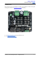
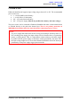
6.MOTORCONNECTION
Similar to the power supply, connection to the motor can be made either via the terminal
block,oritcanbesoldereddirectlytothebottomlayerpad.
For Mixed mode, especially for RC input mode (or Breakout board with Joystick soldered),
each terminal block must be connected to the same side of the motor. For example, left
terminal block connected to motor LEFT and right terminal block connected to motor
RIGHT. User can further test it by controlling the motor by using RC controller. If the motor
givewrongdirection,reversethepolarityofthemotorconnectionattheterminalblock.
CreatedbyCytronTechnologiesSdn.Bhd.–AllRightsReserved 10