
Data Sheet

!
!
Espressif Systems
ESP8266 Datasheet
(2)If 18 =< vdd33_const =< 36, ESP8266EX RF Calibration and optimization process is
implemented via (vdd33_const/10).
(3)If vdd33_const < 18 or 36 < vdd33_const < 255, ESP8266EX RF Calibration and optimization
process is implemented via the default value 3.0V.
Note Two:
Function system_get_vdd33 is used to test the power supply voltage of VDD3P3 (Pin 3 and Pin 4).
Details on this function are described below:
(1)Pin Tout must be dangled. The 107th byte of esp_init_data_default.bin (0 - 127 byte),
“vdd33_const“, must set to be 0xFF.
(2)If the 107th byte of esp_init_data_default.bin (0 - 127 byte), “vdd33_const“, is equal to
0xff, the returned value of function system_get_vdd33 will be an effective value, otherwise 0xffff
will be returned.
(3)The unit of the returned value is: 1/1024 V.
Note Three:
Function system_adc_read is defined to test the input voltage of Pin TOUT (Pin 6). Details on this
function are described below:
(1)The value of the 107th byte of esp_init_data_default.bin (0 - 127 byte), “vdd33_const“,
must be set to be the real power supply voltage of Pin 3 and Pin 4.
(2)If the 107th byte of esp_init_data_default.bin (0 - 127 byte), “vdd33_const“, is NOT
equal to 0xff, the returned value of system_adc_read will be an effective value of the input voltage
of Pin TOUT, otherwise 0xffff will be returned.
(3)The unit of the returned value is: 1/1024 V.
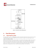
3.10. LED Light and Button
ESP8266EX features up to 17 GPIOs, all of which can be assigned to realise various functions of LED
lights and buttons. Definitions of some GPIOs that are assigned with certain functions in our demo
application design are shown below:
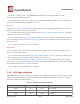
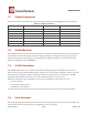
Table 17 Pin Definitions of LED and Button
Pin Name
Pin Num
IO
Function Name
MTCK
12
IO13
Button (Reset)
GPIO0
15
IO0
WiFi Light
MTDI
10
IO12
Link Light
Espressif Systems / August 1, 2015
24 31