ESP8266EX Datasheet Version 4.4 Espressif Systems IOT Team http://bbs.espressif.
ESP8266 Datasheet Espressif Systems Disclaimer and Copyright Notice Information in this document, including URL references, is subject to change without notice. THIS DOCUMENT IS PROVIDED "AS IS" WITH NO WARRANTIES WHATSOEVER, INCLUDING ANY WARRANTY OF MERCHANTABILITY, NON-INFRINGEMENT, FITNESS FOR ANY PARTICULAR PURPOSE, OR ANY WARRANTY OTHERWISE ARISING OUT OF ANY PROPOSAL, SPECIFICATION OR SAMPLE.
ESP8266 Datasheet Espressif Systems Table of Contents 1. 2. 3. General Overview ..................................................................................................6 1.1. Introduction..............................................................................................................6 1.2. Features ....................................................................................................................7 1.3. Parameters .............................................
ESP8266 Datasheet Espressif Systems 4. 3.2. Secure Digital Input/Output Interface (SDIO) ...................................................18 3.3. Serial Peripheral Interface (SPI/HSPI) ..................................................................18 3.3.1. General SPI (Master/Slave) ..................................................................................18 3.3.2. SDIO / SPI (Slave) .................................................................................................
ESP8266 Datasheet Espressif Systems 7.4. 8. Clock Generator ....................................................................................................30 Appendix: QFN32 Package Size.......................................................................
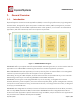
ESP8266 Datasheet Espressif Systems 1. 1.1. General Overview Introduction Espressif Systems’ Smart Connectivity Platform (ESCP) is a set of high performance, high integration wireless SOCs, designed for space and power constrained mobile platform designers. It provides unsurpassed ability to embed WiFi capabilities within other systems, or to function as a standalone application, with the lowest cost, and minimal space requirement.
ESP8266 Datasheet Espressif Systems Espressif Systems’ Smart Connectivity Platform (ESCP) demonstrates sophisticated system-level features include fast sleep/wake context switching for energy-efficient VoIP, adaptive radio biasing for low-power operation, advance signal processing, and spur cancellation and radio co-existence features for common cellular, Bluetooth, DDR, LVDS, LCD interference mitigation. 1.2. Features • 802.
ESP8266 Datasheet Espressif Systems Categories Items Values Certificates FCC/CE/TELEC/SRRC WiFi Protocles 802.11 b/g/n Frequency Range 2.4G-2.5G (2400M-2483.5M) 802.11 b: +20 dBm 802.11 g: +17 dBm Tx Power WiFi Paramters 802.11 n: +14 dBm 802.11 b: -91 dbm (11 Mbps) 802.11 g: -75 dbm (54 Mbps) Rx Sensitivity 802.
ESP8266 Datasheet Espressif Systems AT Instruction Set, Cloud Server, Android/ User Configuration 1.4. iOS App Ultra Low Power Technology ESP8266EX has been designed for mobile, wearable electronics and Internet of Things applications with the aim of achieving the lowest power consumption with a combination of several proprietary techniques. The power saving architecture operates mainly in 3 modes: active mode, sleep mode and deep sleep mode.
ESP8266 Datasheet Espressif Systems • WiFi Location-aware Devices • Security ID Tags • WiFi Position System Beacons Espressif Systems 10/31 August 1, 2015
ESP8266 Datasheet Espressif Systems 2. Hardware Overview 2.1. Pin Definitions The pin assignments for 32-pin QFN package is illustrated in Fig.2. Figure 2 Pin Assignments Table 2 below presents an overview on the general pin attributes and the functions of each pin. Table 2 Pin Definitions Pin Name Type 1 VDDA P Function Analog Power 3.0 ~3.6V RF Antenna Interface. Chip Output Impedance=50Ω 2 LNA I/O No matching required but we recommend that the π-type matching network is retained.
ESP8266 Datasheet Espressif Systems ADC Pin (note: an internal pin of the chip) can be used to 6 TOUT I check the power voltage of VDD3P3 (Pin 3 and Pin4) or the input voltage of TOUT (Pin 6). These two functions cannot be used simultaneously. Chip Enable.
ESP8266 Datasheet Espressif Systems Note: GPIO2, GPIO0, MTDO can be configurable as 3-bit SDIO mode. 2.2. Electrical Characteristics Table 3 ESP8266EX Electrical Characteristics Parameters Conditions Storage Temperature Range Maximum Soldering Temperature Min Typical Max Unit -40 Normal 125 ℃ 260 ℃ 3.6 V IPC/JEDEC JSTD-020 Working Voltage Value I/O 3.0 3.3 VIL/VIH -0.3/0.75VIO 0.25VIO/3.6 VOL/VOH N/0.8VIO 0.
ESP8266 Datasheet Espressif Systems ①: Modem-Sleep requires the CPU to be working, as in PWM or I2S applications. According to 802.11 standards (like U-APSD), it saves power to shut down the WiFi Modem circuit while maintaining a WiFi connection with no data transmission. E.g. in DTIM3, to maintain a sleep 300mswake 3ms cycle to receive AP’s Beacon packages, the current is about 15mA ②: During Light-Sleep, the CPU may be suspended in applications like WiFi switch.
ESP8266 Datasheet Espressif Systems 2.5. MCU ESP8266EX is embedded with Tensilica L106 32-bit micro controller (MCU), which features extra low power consumption and 16-bit RSIC. The CPU clock speed is 80MHz. It can also reach a maximum value of 160MHz. Real Time Operation System (RTOS) is enabled. Currently, only 20% of MIPS has been occupied by the WiFi stack, the rest can all be used for user application programming and development.
ESP8266 Datasheet Espressif Systems Therefore, please choose the correct SPI mode when you are downloading into the flash, otherwise firmwares/programs that you downloaded may not work in the right way. 2.7. AHB and AHB Blocks The AHB blocks performs the function of an arbiter, controls the AHB interfaces from the MAC, SDIO (host) and CPU. Depending on the address, the AHB data requests can go into one of the two slaves: APB block, or flash controller (usually for standalone applications).
ESP8266 Datasheet Espressif Systems 3. Pins and Definitions The chipset encapsulates variable analog and data transmission I/Os, descriptions and definitions of which are explained below in detail. 3.1. 3.1.1. GPIO General Purpose Input/Output Interface (GPIO) There are up to 17 GPIO pins. They can be assigned to various functions by the firmware.
ESP8266 Datasheet Espressif Systems provides protection from over-voltages and ESD. The output devices are also protected from reversed voltages with diodes. 3.2. Secure Digital Input/Output Interface (SDIO) One Slave SDIO has been defined by ESP8266EX, the definitions of which are described in Table 7 below. 4bit 25MHz SDIO v1.1 and 4bit 50MHz SDIO v2.0 are supported. Table 7 Pin Definitions of SDIOs Pin Name 3.3.
ESP8266 Datasheet Espressif Systems 3.3.2. SDIO / SPI (Slave) Table 9 Pin Definitions of SDIO / SPI (Slave) 3.3.3.
ESP8266 Datasheet Espressif Systems Table 11 Pin Definitions of I2C Pin Name Pin Num IO Function Name MTMS 9 IO14 I2C_SCL GPIO2 14 IO2 I2C_SDA Both I2C-Master and I2C-Slave are supported. I2C interface functionality can be realized via software programming, the clock frequency can be up to around 100KHz at most. It should be noted that I2C clock frequency should be higher than the slowest clock frequency of the slave device. 3.5.
ESP8266 Datasheet Espressif Systems Table 13 Pin Definitions of UART Interfaces Pin Type UART0 UART1 Pin Name Pin Num IO Function Name U0RXD 25 IO3 U0RXD U0TXD 26 IO1 U0TXD MTDO 13 IO15 U0RTS MTCK 12 IO13 U0CTS GPIO2 14 IO2 U1TXD SD_D1 23 IO8 U1RXD Data transfers to/from UART interfaces can be implemented via hardware. The data transmission speed via UART interfaces can reach 115200*40 (4.5Mbps). UART0 can be for communication. It supports fluid control.
ESP8266 Datasheet Espressif Systems i.e., between 100Hz and 1KHz. When the PWM frequency is at 1 KHz, the duty ratio will reach 1/22727, and over 14 bit resolution will be achieved at 1KHz refresh rate. 3.8.
ESP8266 Datasheet Espressif Systems The function used to test the input voltage of TOUT is: uint16 system_adc_read(void) RF-init parameter in the following passage refers to esp_init_data_default.bin Application One: Test the power supply voltage of VDD3P3 (Pin 3 and Pin 4). Hardware Design: TOUT must be dangled. RF-init Parameter: The 107th byte of esp_init_data_default.bin (0 - 127 byte), “vdd33_const“, must set to be 0xFF, i.e., the value of “vdd33_const“ is 255.
ESP8266 Datasheet Espressif Systems (2)If 18 =< vdd33_const =< 36, ESP8266EX RF Calibration and optimization process is implemented via (vdd33_const/10). (3)If vdd33_const < 18 or 36 < vdd33_const < 255, ESP8266EX RF Calibration and optimization process is implemented via the default value 3.0V. Note Two: Function system_get_vdd33 is used to test the power supply voltage of VDD3P3 (Pin 3 and Pin 4). Details on this function are described below: (1)Pin Tout must be dangled.
ESP8266 Datasheet Espressif Systems Altogether three interfaces have been defined, one is for the button, and the other two is for LED light. Generally, MTCK is used to control the reset button, GPIO0 is used as an signal to indicate the WiFi working state, MTDI is used as a signal light to indicate communication between the device and the server. Note: Among the nine interfaces mentioned above, most of them can be multiplexed.
ESP8266 Datasheet Espressif Systems 4. Firmware & Software Development Kit The application and firmware is executed in on-chip ROM and SRAM, which loads the instructions during wake-up, through the SDIO interface, from the external flash. The firmware implements TCP/IP, the full 802.11 b/g/n/e/i WLAN MAC protocol and WiFi Direct specification.
ESP8266 Datasheet Espressif Systems • WMM power save U-APSD; • Multiple queue management to fully utilize traffic prioritization defined by 802.11e standard; • UMA compliant and certified; • 802.1h/RFC1042 frame encapsulation; • Scattered DMA for optimal CPU off load on Zero Copy data transfer operations; • Antenna diversity and selection (software managed hardware); • Clock/power gating combined with 802.
ESP8266 Datasheet Espressif Systems Figure 3 Illustration of Power Management 6. 6.1. Clock Management High Frequency Clock The high frequency clock on ESP8266EX is used to drive both transmit and receive mixers. This clock is generated from the internal crystal oscillator and an external crystal. The crystal frequency can range from 26MHz to 52MHz.
ESP8266 Datasheet Espressif Systems Table 18 High Frequency Clock Parameter Symbol Min Max Unit Frequency FXO 26 52 MHz Loading capacitance CL 32 pF Motional capacitance CM 2 5 pF Series resistance RS 0 65 Ω Frequency tolerance ΔFXO -15 15 ppm Frequency vs temperature (-25°C ~ 75°C) ΔFXO,Temp -15 15 ppm 6.2. External Reference Requirements For an externally generated clock, the frequency can range from 26MHz to 52MHz can be used.
ESP8266 Datasheet Espressif Systems 7.1. Channel Frequencies The RF transceiver supports the following channels according to the IEEE802.11b/g/n standards. Table 20 Frequency Channel Channel No Frequency (MHz) Channel No Frequency (MHz) 1 2412 8 2447 2 2417 9 2452 3 2422 10 2457 4 2427 11 2462 5 2432 12 2467 6 2437 13 2472 7 2442 14 2484 7.2. 2.4 GHz Receiver The 2.
ESP8266 Datasheet Espressif Systems ▪ inductor, ▪ varactor, and ▪ loop filter The clock generator has built-in calibration and self test circuits. Quadrature clock phases and phase noise are optimized on-chip with patented calibration algorithms to ensure the best receiver and transmitter performance. 8.