
Data Sheet


ROBOT.HEADtoTOE
ProductUser’sManual–ESPWiFiShieldRev2.0
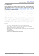
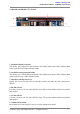
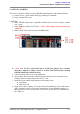
7.ESPResetbutton
ResetbuttonisforconvenienceofusertoresettheonboardESP8266module.
8.Flash/Runslideswitch
Slide switch is for convenience of user to select which mode ESP8266 module will enter
oncepoweredup.
FlashmodethemodewhichESP8266modulewaitforfirmwareinstallation/update
RunmodethemodewhichESP8266moduleruntheinstalledfirmware
9.ESP3V3GPIObreakout
Pin breakout from ESP8266 GPIO, consists of 9 Digital I/O pins and 1 Analog Input pin. All
pinsare3.3Vtolerantonly.
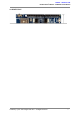
10.PrototypingArea
Prototypingareaforuserstoconstructsmallcircuitssuitabletotheirapplications.
11.PowerLED
Power indicator LED for onboard ESP8266 module. The LED will turn on when 5V power is
suppliedtothemodule.
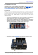
12.RXIndicatorLED
RXLEDasindicatorforRXsignalfromESP8266.
13.TXIndicatorLED
TXLEDasindicatorforTXsignalfromESP8266.
CreatedbyCytronTechnologiesSdn.Bhd.–AllRightReserved 6