
Data Sheet


NCP1117, NCV1117
http://onsemi.com
11
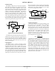
Figure 27. Constant Current Regulator Figure 28. Slow Turn−On Regulator
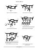
Figure 29. Regulator with Shutdown Figure 30. Digitally Controlled Regulator
Figure 31. Battery Backed−Up Power Supply Figure 32. Adjusting Output of Fixed
Voltage Regulators
The 50 W resistor that is in series with the ground pin of the
upper regulator level shifts its output 300 mV higher than the
lower regulator. This keeps the lower regulator off until the
input source is removed.
Resistor R2 sets the maximum output voltage. Each
transistor reduces the output voltage when turned on.
1
2
Constant Current
Output
3
Input
NCP1117
XTA
++
10
mF
I
out
+
V
ref
R
) I
adj
10
mF
R
1
2
Output
3
Input
NCP1117
XTA
++
10
mF
10
mF
1N4001
R2
R1
10
mF
50 k
2N2907
1
2
Output
3
Input
NCP1117
XTA
++
10
mF
10
mF
120
2N2222
360
1.0 k
1.0 k
Output Control
On
Off
1
2
Output
3
Input
NCP1117
XTA
++
10
mF
10
mF
R1
2N2222
R2
1
50 W
2
Output
3
Input
NCP1117
XT50
++
10
mF
10
mF
+
R
CHG
1
NCP1117
XT50
+
10
mF
−
6.6 V
5.3 V AC Line
5.0 V Battery
1
2
Output
3
Input
NCP1117
XT50
++
10
mF
+
10
mF
10
mF
2.0 k
5.0 V to
12 V
V
out(Off)
+ V
ref
Output Voltage Control
23