
Data Sheet


ROBOT . HEAD to TOE
Product User’s Manual – Shield-Servo
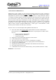
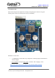
4.BOARD LAYOUT
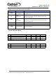
Label
Function
Label
Function
A
UART selector
F
Push button to reset
B
Connector to Servo motor
G
Push button to test
C
Servo motor power indicator
(1 LEDs)
H
Small green LED as VCC indicator
D
Manufacturing test point
I
Voltage input
E
UC00A/UC00C/UC00C
communication
J
Connector to Arduino (Signal)
K
Solder if use internal power
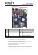
A – A DIP switch used to select TX and RX pin for Shield-Servo.
B – A 8 ways connector for user to connect particular Servo motor. Please insert the
wire properly by referring to chapter 5, Hardware Installation.
C – LEDs acting as indicator for Servo Power. These LEDs will
indicate that Servo is being powered
.
D – Manufacturing test point for Shield-Servo. The header pin is not soldered since it is
meant for production test point. Please DO NOT connect or shorted any of these pins.
Created by Cytron Technologies Sdn. Bhd. – All Rights Reserved