
Data Sheet


ROBOT . HEAD to TOE
Product User’s Manual – Shield-Servo
3. PRODUCT SPECIFICATION AND LIMITATIONS
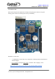
Power Input Pins Function Description
Label
Definition
Function
VM
Servo Supply
Voltage
VM is one of Shield-Servo power sources. VM will supplies
power to Servo motor. Although Shield-Servo provides
protection against wrong polarity for this input, user must
ensure the voltage and polarity of connection are correct
before providing the power so that Shield-Servo can function
correctly.
GND
System Ground
Common ground for both logic operation and Servo motor
power source.
*If power is connect correctly, the PWR LED should light up.
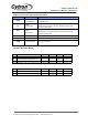
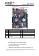
Signal Input Pins Function Description
Label
Definition
Function
TX
Transmit Pin
This pin is TTL/CMOS logic (5V and 0V). Output signal
from Shield Servo transmitted using this pin. Pin available
to use is D1,D3, D11, D13.
RX
Receive Pin
This pin is TTL/CMOS logic (5V and 0V). Input signal to
Shield Servo from arduino transmitted using this pin.Pin
available to use is D0,D2, D10, D12.
UC00A/UC
00C
Control Pin
Pin out for UC00A/UC00C/UC00C.
S1-S8
Signal Out
Output signal to drive the Servo motor. This pin is
TTL/CMOS logic (5V and 0V). Each pulse (logic
change from 0 to 1) will drive the Servo motor.
Created by Cytron Technologies Sdn. Bhd. – All Rights Reserved