
Data Sheet

ROBOT . HEAD to TOE
Product User’s Manual – Shield-Servo
.
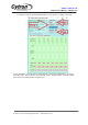
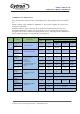
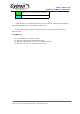
c. 1st byte is combination of mode and servo motor channel. Servo motor channel is from
0-16. Select ‘0’ to activate all servo motor from channel 1 to 8.
0b
1
1
1
X
X
X
X
X
111
Mode for position and speed command
00000-01000
Servo motor channel
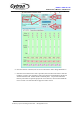
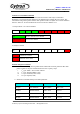
d. 2nd and 3rd byte combined to provide 13 bit data of servo position, 0-8000. The
resolution
of Shield-servo is 0.5us. It will start from 0.5ms and increase the duty cycle of pulses
according to value of position. Thus, following formula show the duty cycle of pulse
generated.
.Duty cycle = (resolution X servo position)+0.5ms
=(0.25us X servo position)+0.5ms
0b
0
X
X
X
X
X
X
X
12
11
10
9
8
7
6
2nd Byte: Higher 7 bit
0b
0
0
X
X
X
X
X
X
5
4
3
2
1
0
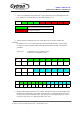
3rd Byte: Lower 6bit
0b
X
X
X
X
X
X
X
X
X
X
X
X
X
12
11
10
9
8
7
6
5
4
3
2
1
0
13 bit servo position
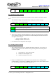
e. 4th byte represents the speed of servo rotation. The speed is from 0-100. The higher value
the faster servo will rotate to its position. Decimal value ‘1’ indicates that the servo will
run at slowest speed and decimal value ‘100’ will run at fastest speed. However, value ‘0’
is special value. Value ‘0’ is more faster than value ‘100’.
Created by Cytron Technologies Sdn. Bhd. – All Rights Reserved