SHIELD-Servo Servo Controller Shield User’s Manual V1.
ROBOT . HEAD to TOE Product User’s Manual – Shield-Servo Index 1. Introduction and Overview 3 1.0 Introduction of SHIELD-Servo 3 1.1 System Overview 4 1.2 How RC Servo Motor Works 5 2. Packing List 6 3. Product Specification and Limitations 7 4. Board Layout 9 4.1 Dimension 5. Installation (hardware) 10 11 5.1 Setting up Shield-Servo 11 5.2 Connecting to Arduino UNO/CT-UNO using Signal Pin 13 5.3 Connecting to External Switches 14 5.
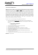
ROBOT . HEAD to TOE Product User’s Manual – Shield-Servo INTRODUCTION AND OVERVIEW 1.0 Introduction of SHIELD-Servo SHIELD-Servo offers reliable yet user friendly RC (Radio Control) Servo motor controller to hobbyist and students. Different with SC16A and SC08A, SHIELD-Servo is designed to control 8 independent RC (Remote Control) Servo motors simultaneously in a single board with a built in 5V 5Ampere switching regulator. Each Servo signal pin is able to generate Servo pulses with duty cycle from 0.
ROBOT . HEAD to TOE Product User’s Manual – Shield-Servo 1.1 System Overview Shield-Servo is the enhanced version from SC08A. One of the additional features for Shield-Servo compare to SC08A is the onboard Voltage regulator and UC00A/UC00C interface for easiest uart communication or connect directly to SKXBee. UART is provided in Shield-Servo for easier communication between user’s circuit (microcontroller/Arduino) and Shield-Servo.
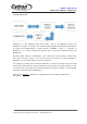
ROBOT . HEAD to TOE Product User’s Manual – Shield-Servo 1.2 How RC Servo Motor Works RC Control hobby Servos are small actuators designed for remotely operating model vehicles such as cars, airplanes, and boats. Nowadays, Servos are become more popular in robotics, creating humanoid robot, biologically inspired robot, robotic arm and etc. This is because its ability to rotate and maintain at certain location, position or angle according to control pulses from a single wire.
ROBOT . HEAD to TOE Product User’s Manual – Shield-Servo 2. PACKING LIST Please check the parts and components according to the packing list. If there are any parts missing, please contact us at sales@cytron.com.my immediately. Shield-Servo comes with: • 1 x SHIELD-Servo board with every component is soldered properly and tested before board is shipped. User’s Manual and sample source codes (in VB.net and C language) can be downloaded from https://www.cytron.com.
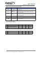
ROBOT . HEAD to TOE Product User’s Manual – Shield-Servo 3. PRODUCT SPECIFICATION AND LIMITATIONS Power Input Pins Function Description Label VM Definition Servo Supply Voltage Function VM is one of Shield-Servo power sources. VM will supplies power to Servo motor. Although Shield-Servo provides protection against wrong polarity for this input, user must ensure the voltage and polarity of connection are correct before providing the power so that Shield-Servo can function correctly.
ROBOT . HEAD to TOE Product User’s Manual – Shield-Servo UART/UC00A/UC00C Pins Function Description Label Definition Function RESET Pin via Connected to Reset pin via 0.1uF capacitor. Suitable to act DTR 0.1uF capacitor as software reset. This is UART transmit pin. It should be UART TX interfaced to 5V logic UART. It should be connected Transmit Pin to host’s receive pin. This is UART receive pin. It should be RX UART interfaced to 5V logic UART. It should be connected Receive Pin to host’s transmit pin.
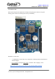
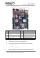
ROBOT . HEAD to TOE Product User’s Manual – Shield-Servo 4.BOARD LAYOUT Label A B C D E K Function UART selector Connector to Servo motor Servo motor power indicator (1 LEDs) Manufacturing test point UC00A/UC00C/UC00C communication Solder if use internal power Label F G Function Push button to reset Push button to test H Small green LED as VCC indicator I Voltage input J Connector to Arduino (Signal) A – A DIP switch used to select TX and RX pin for Shield-Servo.
ROBOT . HEAD to TOE Product User’s Manual – Shield-Servo E – UART communication between Shield-Servo and PC’s Serial Communication Interface (SCI). F – A push button acting as reset button. If this button is pressed, Shield-Servo will be reset to initial stage. Please DO NOT pressed this button during operation . G – A push button to activate self test. When it is pressed and release, Shield-Servo will start to drive Servo motor. H – A small green LED to indicate status of power.
ROBOT . HEAD to TOE Product User’s Manual – Shield-Servo 4.1 DIMENSION Created by Cytron Technologies Sdn. Bhd.
ROBOT . HEAD to TOE Product User’s Manual – Shield-Servo 5. INSTALLATION (HARDWARE) 5.1 Setting up Shield-Servo Shield-Servo is designed to control 8 channels of RC Servo motor. Following steps will guide user in using this shield. Before connection can be made, please determine the correct polarity for power supply. In general, DC power supply only have 2 wire which is red and black. The best solution is to obtain the polarity and voltage by measure using multimeter.
ROBOT . HEAD to TOE Product User’s Manual – Shield-Servo 5.2 Connecting to Arduino UNO/CT-UNO using signal pin. Typical application would require a Arduino to communicate with Shield-Servo using UART/Serial communication. This pin has the function to Transmit and Receive signal. Please refer to tutorial of Software serial from Arduino website for details of using Software serial. Please note that if you are using internal power to power up Servo, dont use VM from 12V or another power supply.
ROBOT . HEAD to TOE Product User’s Manual – Shield-Servo 5.4 Connecting to Computer through UART 5.4.1 Connecting Shield-Servo to Computer Another concern in controlling Servo motor using a computer is the hard work needed to get started. However, with Shield-Servo, interfacing with a computer is as easy as 1 2 3. Normally, user will need to develop a RS232 level shifter for communication to serial port. This generates extra work.
ROBOT . HEAD to TOE Product User’s Manual – Shield-Servo 6. INSTALLATION SOFTWARE There are 2 options of sample software being provided for Shield-Servo. The simplest way is to use sample program for Arduino, while another option is the use sample GUI program to control Servo motors through Shield-Servos. 6.1 Sample Program for Computer To ease user in using Shield-Servo, Cytron Technologies has developed a Shield-Servo GUI using VB.net for user to control Shield-Servo from computer through a COM Port.
ROBOT . HEAD to TOE Product User’s Manual – Shield-Servo 4. A window as shown in the figure below pops up. 5. Before any setup can be done, please ensure hardware installation of Shield-Servo is being setup correctly and power to Servo motor is connected. If you are using UC00A/UC00C, UC00A/UC00C’s driver must be installed. 6. After hardware installation, choose the correct COM Port. Normally, the extra virtual COM port will be the largest number port after driver installation. Select it.
ROBOT . HEAD to TOE Product User’s Manual – Shield-Servo 7. Click the “Connect” button and Shield-Servo GUI will show “COMxx connected”. 8. Now, Shield-Servo GUI is ready to control the Servo motor using Shield-Servo. User may on/off the motor, Active/deactive the individual motor, change position, set motor rotation speed, reset servo initial position using this GUI. Created by Cytron Technologies Sdn. Bhd.
ROBOT . HEAD to TOE Product User’s Manual – Shield-Servo 6.2 Sample Program for CT-Uno Driving Servo motor is common necessity in most robotic project based on the embedded system which uses microcontroller. Considering this reason, Cytron Technologies has also developed the sample source code for Arduino. This sample program is developed for CT-UNO.
ROBOT . HEAD to TOE Product User’s Manual – Shield-Servo 7. GETTING STARTED This section will show how to get started with Shield-Servo and connect to UART communication. 1st example is using Shield-Servo with computer and 2nd example is using Shield-Servo with Microcontroller. 7.1 Using Shield-Servo with computer After installation of Shield-Servo GUI and UC00A/UC00C driver, user is ready to use Shield-Servo with computer/laptop. a. Setup Shield-Servo according to steps in 5.4.2.
ROBOT . HEAD to TOE Product User’s Manual – Shield-Servo d. Once the status is connected, user is free to control Servo motor using Shield-Servo. e. Since the GUI VB.net source code is provided, user can refer to the source code and modify it or write a new program to create own GUI for own application. The GUI is written with Microsoft Visual Studio Community 2015. Any version older than this may not be able to open the project file.
ROBOT . HEAD to TOE Product User’s Manual – Shield-Servo 7.2 Shield-Servo UART Protocol If you are using the UART protocol to control Shield-Servo, both computer and microcontroller are actually sending serial command to Shield-Servo. This section explains the protocol for send/receive commands. Shield-Servo has two types of protocol, the 1st protocol is important which is uses to send command to Shield-Servo, further control a particular servo to a position with a defined speed.
ROBOT . HEAD to TOE Product User’s Manual – Shield-Servo Activate Servo Channel Command The initial status for servo motor is deactivated. Host need to sends 2 byte command to Shield-Servo to On/Off selected channels or all channels before running the servo motor. The command is being send in packet format. Each packet consists of 2 bytes. Servo motor channel is from 0-8. Select ‘0’ to activate/deactivate all servo motor fro channel 1 to 8. i.
ROBOT . HEAD to TOE Product User’s Manual – Shield-Servo . c. 1st byte is combination of mode and servo motor channel. Servo motor channel is from 0-16. Select ‘0’ to activate all servo motor from channel 1 to 8. 0b 1 1 1 X X X 111 Mode for position and speed command 00000-01000 Servo motor channel X X d. 2nd and 3rd byte combined to provide 13 bit data of servo position, 0-8000. The resolution of Shield-servo is 0.5us. It will start from 0.
ROBOT . HEAD to TOE Product User’s Manual – Shield-Servo 0b 0 X X X X X X X Servo motor speed 0-100 Servo position reporting command a. If position report is needed, the host (Arduino) need to send this command to Shield servo. The command is being send in packet format Each packet consists of a byte: 1st Byte: Mode + servo motor channel 0b 1 0 1 X X X X X Mode for position reporting command Servo motor channel (1-8). If ‘0’, command not executed. b.
ROBOT . HEAD to TOE Product User’s Manual – Shield-Servo Mode for servo starting position command Servo motor channel c. 2nd and 3rd byte is combined to provide 13 bit servo position. Please refer back Position and speed command section for description for these byte. d. After received starting position command, Shield servo will reply one byte 0x04 to microcontroller. 8. WARRANTY ❖ ❖ ❖ ❖ Product warranty is valid for 6 months. Warranty only applies to manufacturing defect.
ROBOT . HEAD to TOE Product User’s Manual – Shield-Servo Prepared by Cytron Technologies Sdn. Bhd. 19, Jalan Kebudayaan 1A, Taman Universiti, 81300 Skudai, Johor, Malaysia. Tel: +607-521 3178 Fax: +607-521 1861 URL: www.cytron.com.my Email: support@cytron.com.my sales@cytron.com.my Created by Cytron Technologies Sdn. Bhd.