
Data Sheet

ROBOT . HEAD to TOE
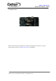
Product User’s Manual – URC10
GND
System Ground
Common ground for both logic operation and stepper motor
power source.
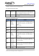
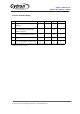
The truth table for the control logic for motor 1 and motor 2 are as follow:
PWM
DIR
Output A
Output B
Low
X(Don’t care)
Low
Low
High
Low
High
Low
High
High
Low
High
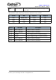
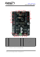
Pin No
Pin Name
Description
M1A
Motor 1 Output A
Connect to motor 1 terminal A
M1B
Motor 1 Output B
Connect to motor 1 terminal B
VM
POWER +
Positive Supply (positive terminal of battery)
GND
POWER -
Negative Supply (negative terminal of battery)
M2A
Motor 2 Output A
Connect to motor 2 terminal A
M2B
Motor 2 Output B
Connect to motor 2 terminal B
Created by Cytron Technologies Sdn. Bhd. – All Rights Reserved