
Data Sheet

ROBOT . HEAD to TOE
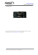
Product User’s Manual – URC10
3. PRODUCT SPECIFICATION AND LIMITATIONS
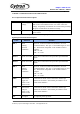
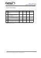
Power Input Pins Function Description
Label
Definition
Function
VM
Motor Supply
Voltage
VM is for board power sources. VM will supplies power to
both motor and controller circuit. User must ensure the
voltage and polarity of connection are correct before providing
the power so that Mono can function correctly.
GND
System Ground
Common ground for both logic operation and stepper motor
power source.
*If power is connect correctly, the PWR LED should light up.
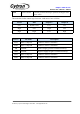
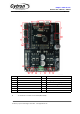
Signal Input Pins Function Description
Label
Definition
Function
DIR 1
Motor
Rotating
Direction
Control Pin
Input for motor 2 to rotate CW (clockwise) or CCW
(counterclockwise). This pin is TTL/CMOS logic (5V and
0V). The direction is depends on the Arduino code For
example:
DIR = 0V CW
DIR = 5V CCW
PWM 1
Speed control Pin
Input pin to Control the motor speed.This pin need PWM
signal.
PWM 2
Speed control Pin
Input pin to Control the motor speed.This pin need PWM
signal.
DIR 2
Motor
Rotating
Direction
Control Pin
Input for motor 2 to rotate CW (clockwise) or CCW
(counterclockwise). This pin is TTL/CMOS logic (5V and
0V). The direction is depends on the Arduino code For
example:
DIR = 0V CW
DIR = 5V CCW
TRIG
Sonar Sensor
trigger Pin:
Sensor 1- D9
Sensor 2- D11
Connection for Sonar sensor connected to Arduino pin
number D9 for Sonar 1 and Arduino pin number D11 for
Sonar sensor number 2.
ECHO
Sonar Sensor
Echo pin:
Sensor 1- D8
Sensor 2- D10
Connection for Sonar sensor connected to Arduino pin
number D8 for Sonar 1 and Arduino pin number D10 for
Sonar sensor number 2.
+5V
5V Output
5V output to power up sensor.
Created by Cytron Technologies Sdn. Bhd. – All Rights Reserved